Question-and-Answer Resource for the Building Energy Modeling Community
First time here? Check out the Help page!
| 2020-11-11 12:28:03 -0500 | received badge | ● Notable Question (source) |
| 2020-06-07 10:46:32 -0500 | received badge | ● Popular Question (source) |
| 2017-09-19 13:17:38 -0500 | received badge | ● Popular Question (source) |
| 2015-12-11 09:15:28 -0500 | asked a question | Natural ventilation to reduce cooling loads I'm modeling a very simple house with a single thermal zone with CAV DX coil cooling with a single air duct. In order to test cooling loads reduction with window opening, I constructed a simple AFN for natural ventilation, using NoMultizoneOr Distribution and Surface Average Calculation method (I am a novice to Airflownetwork (AFN) though). However, even though the AFN is set, I find no change in cooling loads. Can anyone explain why? and how to fix this problem? Thanks in advance. My inputs are as follows: |
| 2015-12-09 15:56:26 -0500 | asked a question | Required Field data to get Fanger PMV? Could anyone tell me which parameters are required to get Output:Variable FangerPMV in EnergyPlus (v.7.2)? It seems to me that I inputted data rightly, but shows no PMV results in ESO file. Field data in People class that I provided include: - Activity Schedule - Mean Radiant Temperature Calculation Type - Work Efficiency Schedule - Clothing Insulation Schedule - Air Velocity Schedule - Thermal Comfort Model 1 Type... |
| 2015-12-09 06:40:40 -0500 | received badge | ● Teacher (source) |
| 2015-12-08 21:59:45 -0500 | answered a question | How to evaluate indoor comfort The variable name for EP 7.2.0 is little different. Output:Variable, *,FangerPMV, hourly; |
| 2015-12-08 21:40:05 -0500 | commented answer | Is Schedule:Day:Interval not available for Actuated Component Type? Thanks, Sharma. By the way, I found the following is more useful to check out available actuators. Output:EnergyManagementSystem, |
| 2015-12-08 18:50:41 -0500 | asked a question | Is Schedule:Day:Interval not available for Actuated Component Type? I'm interested in dynamic scheduling of heat/cool setpoint, and added the following code in my idf file. !- ========== EMS: Sensory Control ================= EnergyManagementSystem:Sensor, EnergyManagementSystem:ProgramCallingManager, EnergyManagementSystem:Actuator, EnergyManagementSystem:Program, This works, but I'd like to change Schedule:Constant, !- Actuated Component Type to a difference object such as Schedule:Day:Interval. However, it does not work. Does EMS not recognize the object, even though it is obviously an object in IDD file? Can anyone answer? |
| 2015-05-14 09:41:32 -0500 | asked a question | Meaning of Zone Energy Transfer in Meter Output? Can anyone help me interpret the following item of Energyplus meter outputs in mdd? Output:Meter,Heating:EnergyTransfer:Zone. Can this be understood as an amount of actual energy delivery from HVAC to a thermal zone? |
| 2015-05-01 20:24:43 -0500 | commented question | No heating/cooling load in district heat/cooling with Radiative systems @Amir Roth Thanks for your editing:) |
| 2015-05-01 19:24:35 -0500 | asked a question | No heating/cooling load in district heat/cooling with Radiative systems I designed a plant loop for a small house with radiant heating and cooling equipment for a single zone as shown in Figure 1 (district heating/cooling + low-temp radiant variable). Open studio simulation worked, but the result showed no heating and cooling load for the zone (figure 3). I struggled for fixing this trouble, but no answer for now. I guess my problem is involved with setting up schedules for the radiant system and the plant loop. Can you suggest any insightful idea for me?? Thanks very much!
|
| 2015-04-30 23:06:50 -0500 | marked best answer | How to model GSHP with radiant floor heating in OpenStudio? I design a small house, using OpenStudio 1.7.2, with a ground source heat pump (GSHP) for space heating, cooling, and hot water use. But I've got a serious trouble in modeling HVAC. Overall scheme is like this: (1) the main system is GSHP (2) space conditioning is supplied by underfloor radiant heating and cooled air from a terminal unit mounted on the ceiling. That is, water heated by GSHP circulates underfloor tubes, and chilled water coil exchanges heat with outdoor air to cool the air during summer. I think water-to-water GSHP is desirable for heating, and water-to-air for cooling. However, I have no idea of how to combine those water-based loop and air loop to support for a single thermal zone. Please let me know if you possibly know how to construct GSHP with radiant floor heating without implementing "district heating or cooling" plant object. Best |
| 2015-04-30 22:53:08 -0500 | received badge | ● Scholar (source) |
| 2015-04-30 22:51:37 -0500 | commented answer | How to model GSHP with radiant floor heating in OpenStudio? Thanks so much, Matthew. I appreciate your quick response and detailed illustration. The tutorial you linked was so helpful that I could model GSHP, GLHEPro seems not for free though. However, there still remains a problem, like plugging radiant heating system into the WSHP. It seems to me yours also doesn't look like low temp radiant heating/cooling. A tutorial for radiant conditioning suggests to use HW boiler as a supply equipment. That said, I thought WSHP could also make sense, and attempted to connect the radiant equipment to WSGP, but heat/cooling load resulted in blank.... |

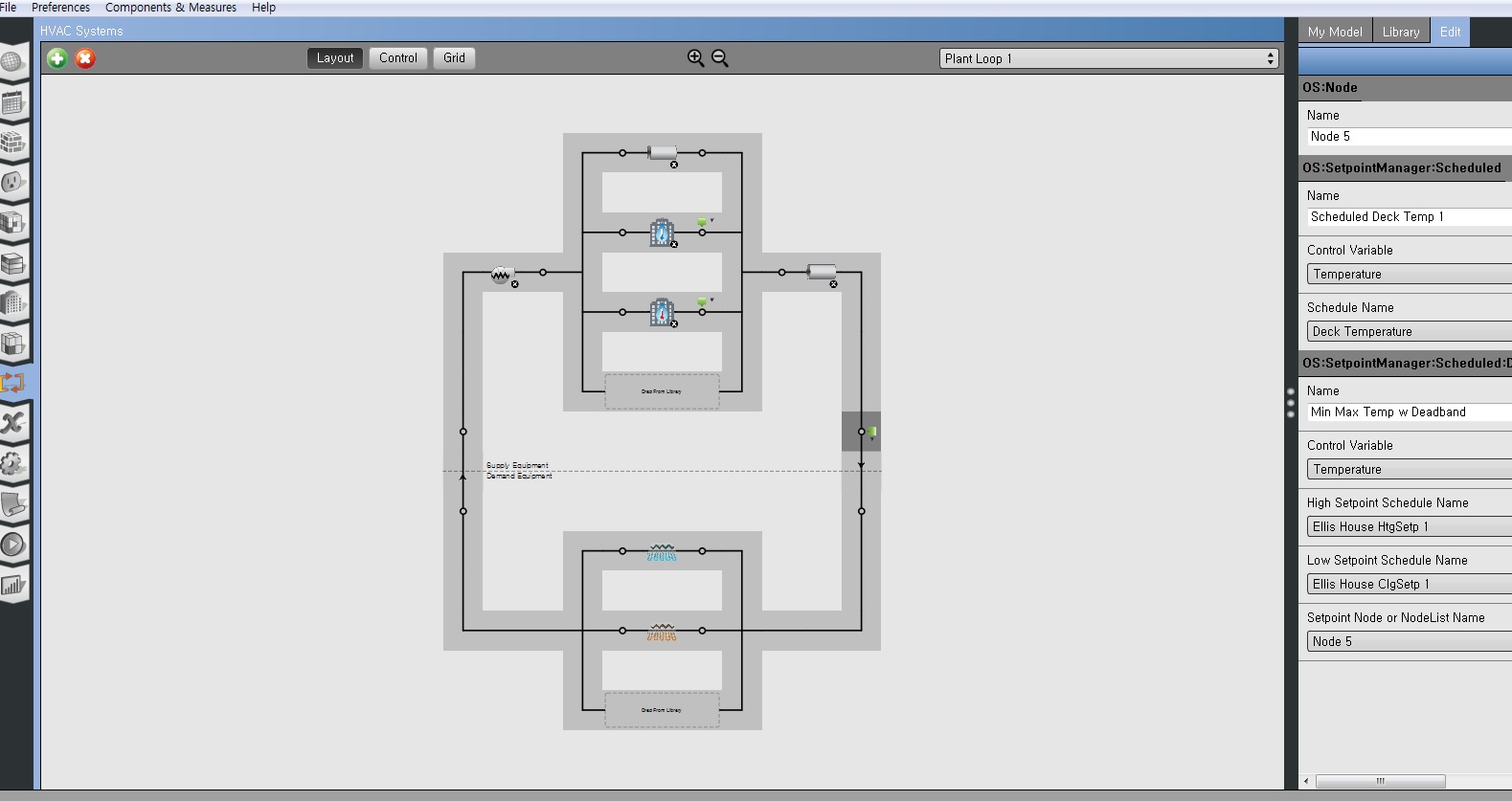 Figure 1
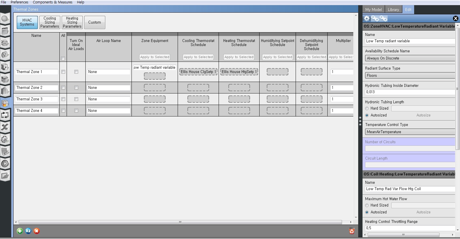 Figure 2
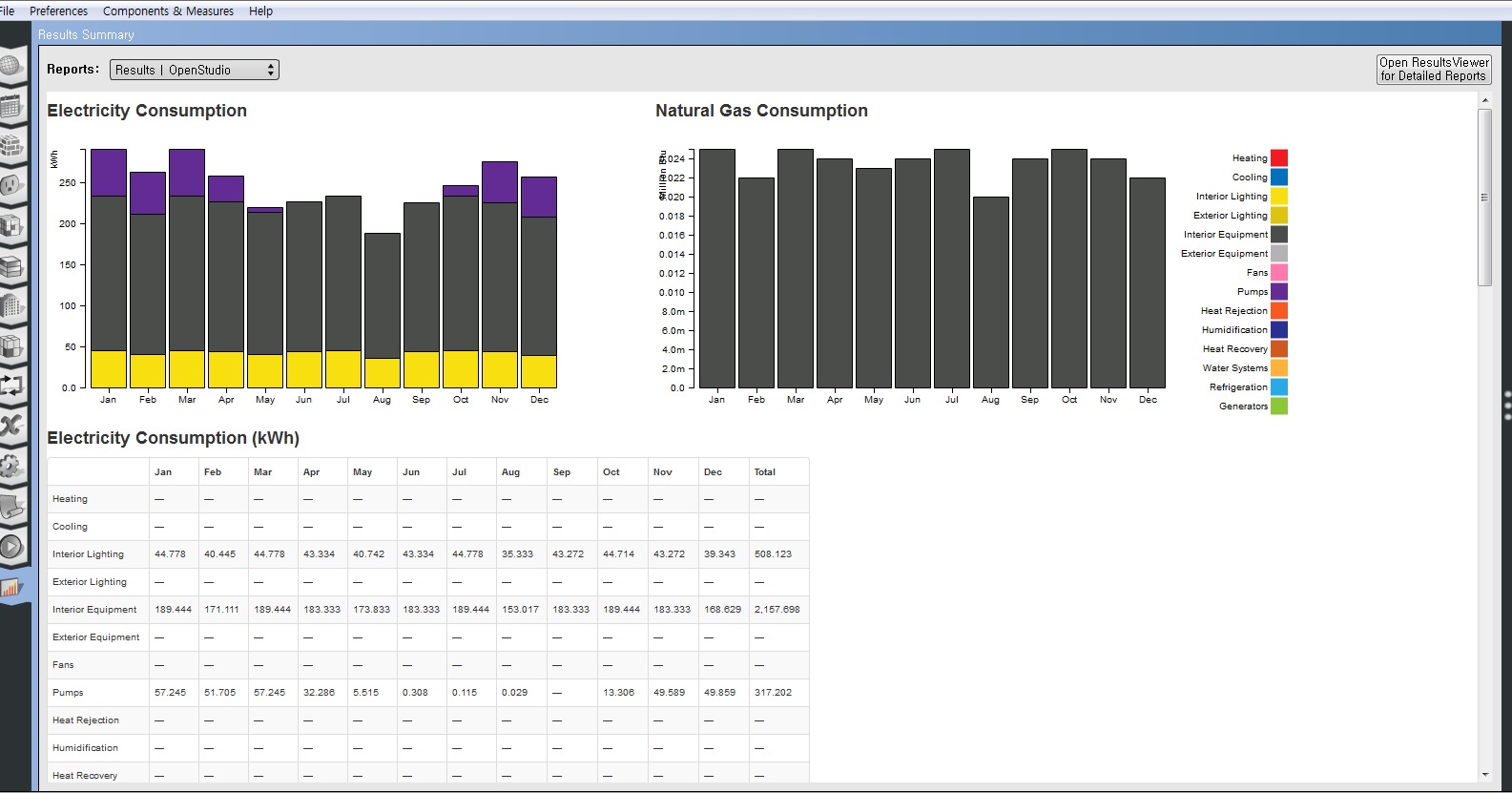 Figure 3