

Hi All, I'm working on a complex chilled water plant on EnergyPlus via DesigBuilder, whose mai goal is to properly activate the chilling resources based on their capacity and COP that vary with external conditions (dry-cooler, open loop ground water source wells, air cooled water chiller ,...).
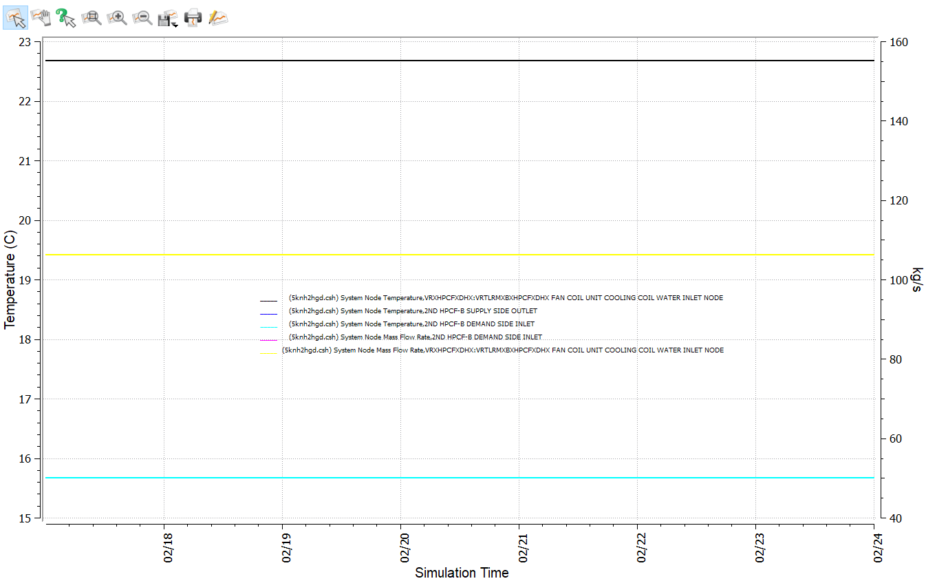
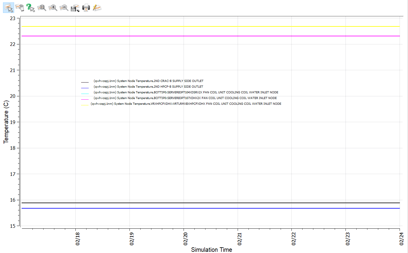
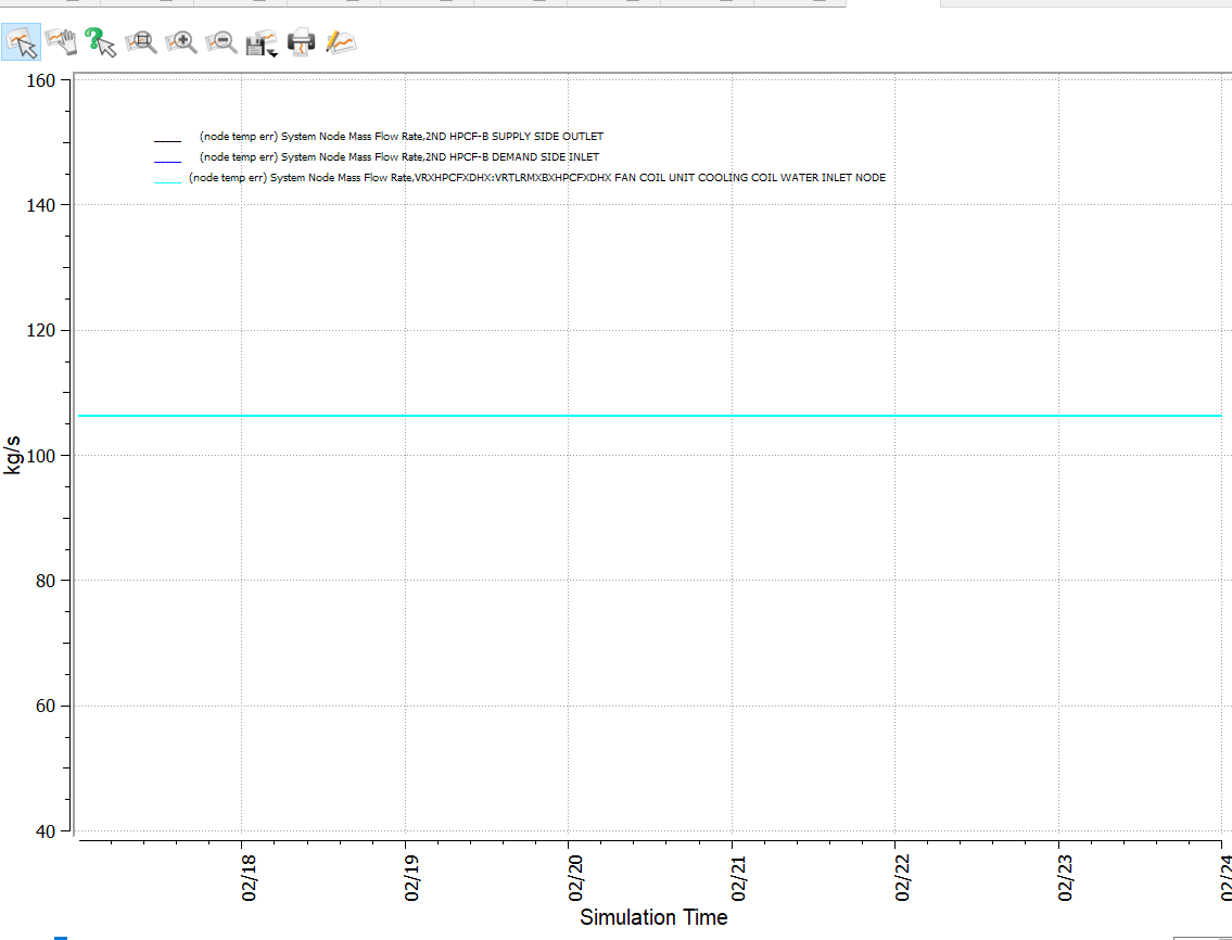
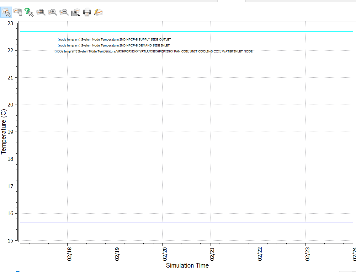
I spent many efforts without achieving a satisfactory solution (maybe the only effective solution is through the EMS... sorry for sharing the frustration), but what i found really disappointing are intermediate results that are impossible: in more than one chilling resources configuration I found that the inlet temperature to the water terminals ARE DIFFERENT than the outlet supply-side temperature of the same loop: 15,7 °C at the supply side outlet node vs. 22,7 °C at the inlet of the FCU cooling coil (2nd HPFC-B loop) 15,9 °C vs 22,3 °C (2nd CRAC-B)
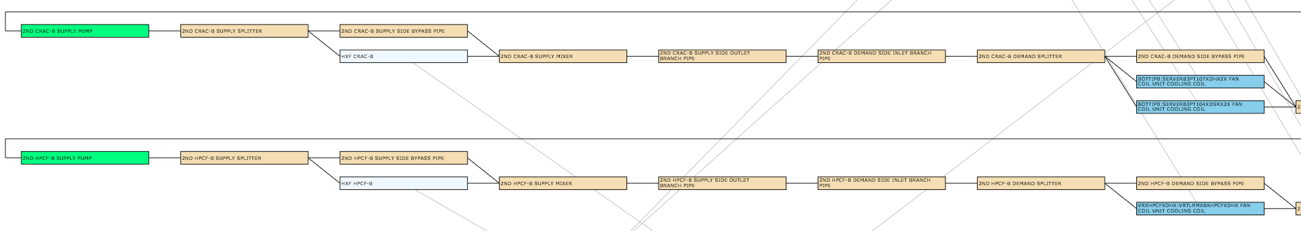
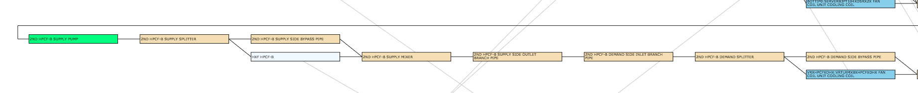
Here two link to the graph and the scheme for a better understanding and for illustrating that the differencies are on THE SAME LOOP (scheme is a screnshot from the .svg file generated by EnergyPlus).
I cannot guess how this is possible.
Any contribution is welcome
Best regards Alessandro


