Question-and-Answer Resource for the Building Energy Modeling Community
Get started with the Help page
Ask Your Question
1

Inconsistent Chilled Water Node Temperatures

asked 2020-03-18 14:23:59 -0500

updated 2020-07-03 09:53:51 -0500

Hi All,

I'm working on a complex chilled water plant on EnergyPlus via DesigBuilder, whose main goal is to properly activate the cooling resources based on their capacity and COP that vary with external conditions (dry-cooler, open loop ground water source wells, air cooled water chiller ,...).

I spent many efforts without achieving a satisfactory solution (maybe the only effective solution is through the EMS... sorry for sharing the frustration), but what i found really disappointing are intermediate results that are impossible: in more than one cooling resources configuration I found that the inlet temperature to the water terminals ARE DIFFERENT than the outlet supply-side temperature of the same loop:

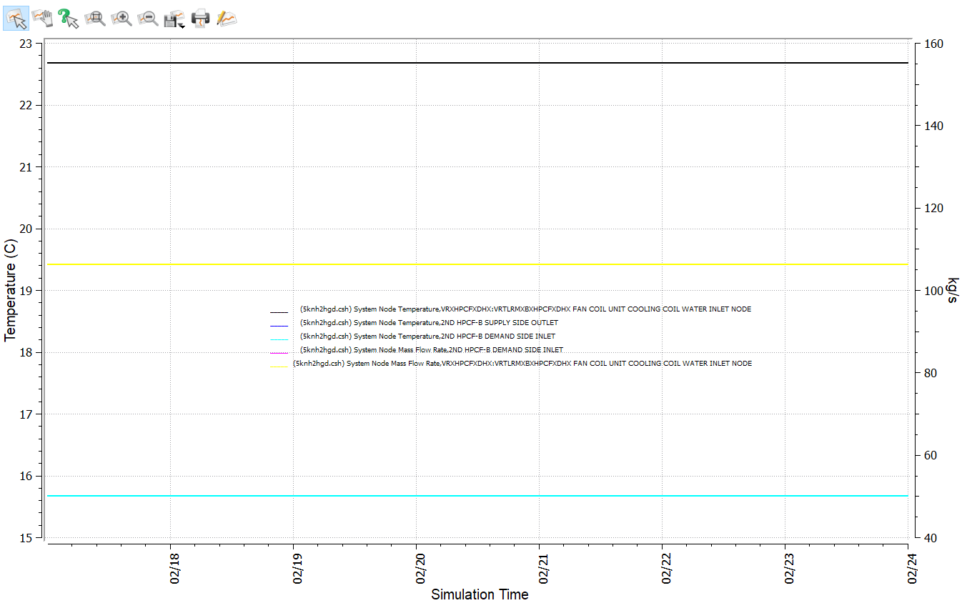
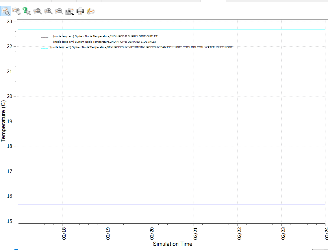
15,7 °C at the supply side outlet node vs. 22,7 °C at the inlet of the FCU cooling coil (2nd HPFC-B loop)

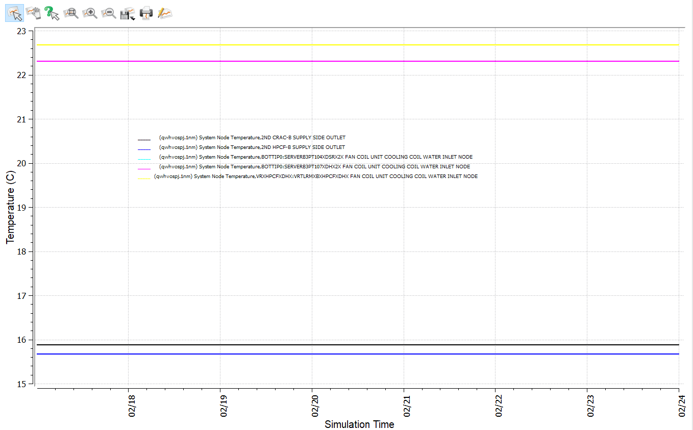
15,9 °C vs 22,3 °C (2nd CRAC-B)

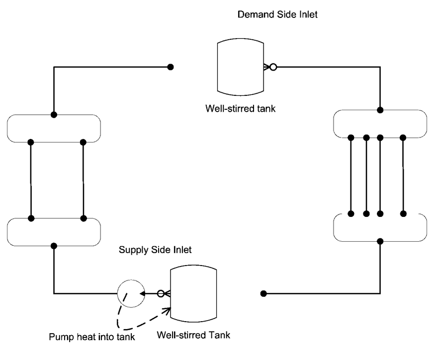
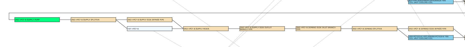
Here two link to the graph and the scheme for a better understanding and for illustrating that the differencies are on THE SAME LOOP (scheme is a screnshot from the .svg file generated by EnergyPlus).

C:\fakepath\node temp.png

C:\fakepath\scheme svg.png

I cannot guess how this is possible.

Any contribution is welcome

Best regards

Alessandro

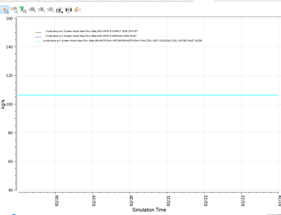
Here another graph: node temps at supply side outlet node = node temp at demand side inlet node (light blue over blu line), and about mass flow rates (yellow line over magenta line)

image description


Update:

So, do I have to think it is a sort of "bug" of the plant solver (taht is: the software does not work properly itself)?

Ag


2nd Update:

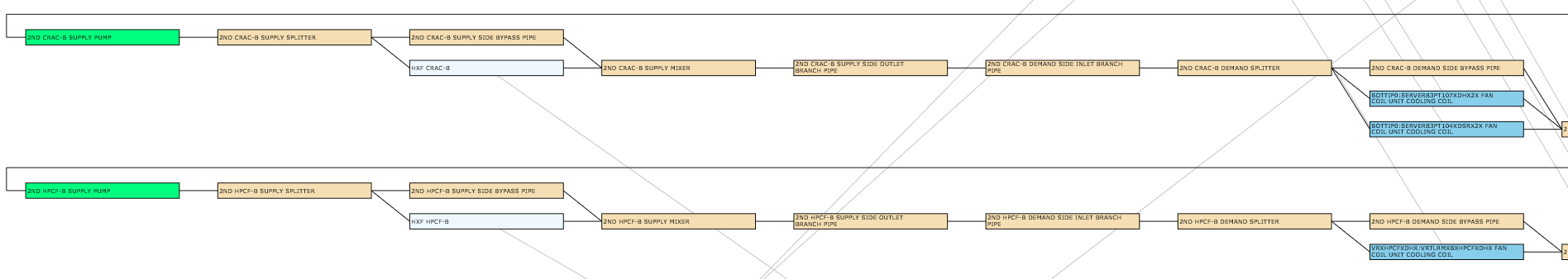
I've used only adiabatic pipes, so there are no thermal losses along pipes.

Now I've atteched three images about the three nodes to focus on (according to the order with which they appear in the circuit):

  • 2ND HPFC-B SUPPLY SIDE OUTLET

  • 2ND HPFC-B DEMAND SIDE INLET

  • VRXHPCFXDHX:VrtlRmXBXHPCFXDHX Fan Coil Unit Cooling Coil Water Inlet Node

image 1: plant branches scheme

image 2: node water mass flow rates

image 3: node chilled water temperatures

then a link to the IDF file

edit retag flag offensive close merge delete

Comments

hello, may how I know how did you solve this problem?

larry liong's avatar larry liong  ( 2024-04-04 22:00:32 -0500 )edit

2 Answers

Sort by » oldest newest most voted
2

answered 2020-03-18 17:10:45 -0500

updated 2020-03-26 08:30:33 -0500

Without looking at the EnergyPlus IDF, I would first confirm that this happens when there is chilled water flow by adding a "System Node Mass Flow Rate" output variable for the supply-side outlet node to these charts. If these temperature differences occur when there is no chilled water flow, then you don't have an issue.

If these temperature differences occur when there is chilled water flow, then next I would confirm that this is also looking at the final node leaving the supply-side of the loop and not the outlet node directly after each HXF component. This HXF outlet water can mix with the water flowing through the parallel bypass pipes, causing increased temperatures on the demand side.

If both of those things are confirmed, then this is behavior is likely due to low loop volume, low loop flow rates, or low loop fluid heat capacity that affects the way that EnergyPlus accounts for liquid heat storage capacity and pump friction. For the supply and demand sides of water plant loops, EnergyPlus uses an "imaginary" storage tank at the first inlet node that changes the water temperature there. If you were to compare temperatures of supply-side outlet node to demand-side inlet node, even though they are immediately in series, they will be different values because of this (unless you set the loop heat capacitance to zero). See screenshot below from the Engineering Reference section I linked to above.

image description

To confirm that this is the case, you can add "Plant Supply Side Lumped Capacitance Heat Storage Rate" and similar output variables to investigate if this is causing the temperature differences you see.

UPDATE

Thanks for adding demand inlet node temperatures and flow rates to the chart, that helps. If the temperature for supply side outlet node and demand side inlet node are equal, then it's not the imaginary storage tank and also likely not the plant loop iterations. One other possible explanation is that you have pipes with sleeve losses instead of adiabatic pipes. This would explain warming of chilled water after supply outlet node and before reaching the fan coil. It's hard for us to know the proper solution without seeing your IDF, if you can link to the IDF it would be great.

edit flag offensive delete link more

Comments

@Aaron Boranian thank you for your reply:

1- Yes, there is flow on both loops (I added an image to the orignial post: the flow through the VRTLR... coil is the same of that of the HPCF-B loop: it is the only terminal served by the loop);

2- Temp. on supply side outlet node is the same of that at the demand side inlet node (see the same previous picture), so the problem is not on the imaginary starage tank;

3- Loops have high flow rates becouse of high internal gains, but also quite great volumes (more than 4 and 9 cubic meters for CRAC-B and HPCF-B respectively).

I'm still confused about

Ag's avatar Ag  ( 2020-03-19 12:22:23 -0500 )edit

'> Thank you for your insights

Ag's avatar Ag  ( 2020-03-19 12:22:42 -0500 )edit
2

answered 2020-03-18 18:56:01 -0500

It is possible that the adjacent nodes have different temperatures because the plant solver is not converging. You could try increasing the number of Minimum Plant Iterations.

edit flag offensive delete link more

Comments

@shorowit Thank you for your replay. In the ERR file I've no Warning (or Severe Error) related to convergence. But I've these warnings (same for CRAC-B loop), maybe related to the problemo I'm facing. The plants should work at 15 °C as the supply side is close to do

* Warning * Plant Loop: 2ND HPCF-B Demand Side is storing excess heat the majority of the time. * Warning * Plant Loop: 2ND HPCF-B Supply Side is storing excess heat the majority of the t

Ag's avatar Ag  ( 2020-03-19 12:02:43 -0500 )edit

Your Answer

Please start posting anonymously - your entry will be published after you log in or create a new account.

Add Answer

Careers

Question Tools

1 follower

Stats

Asked: 2020-03-18 14:23:59 -0500

Seen: 414 times

Last updated: Jul 03 '20