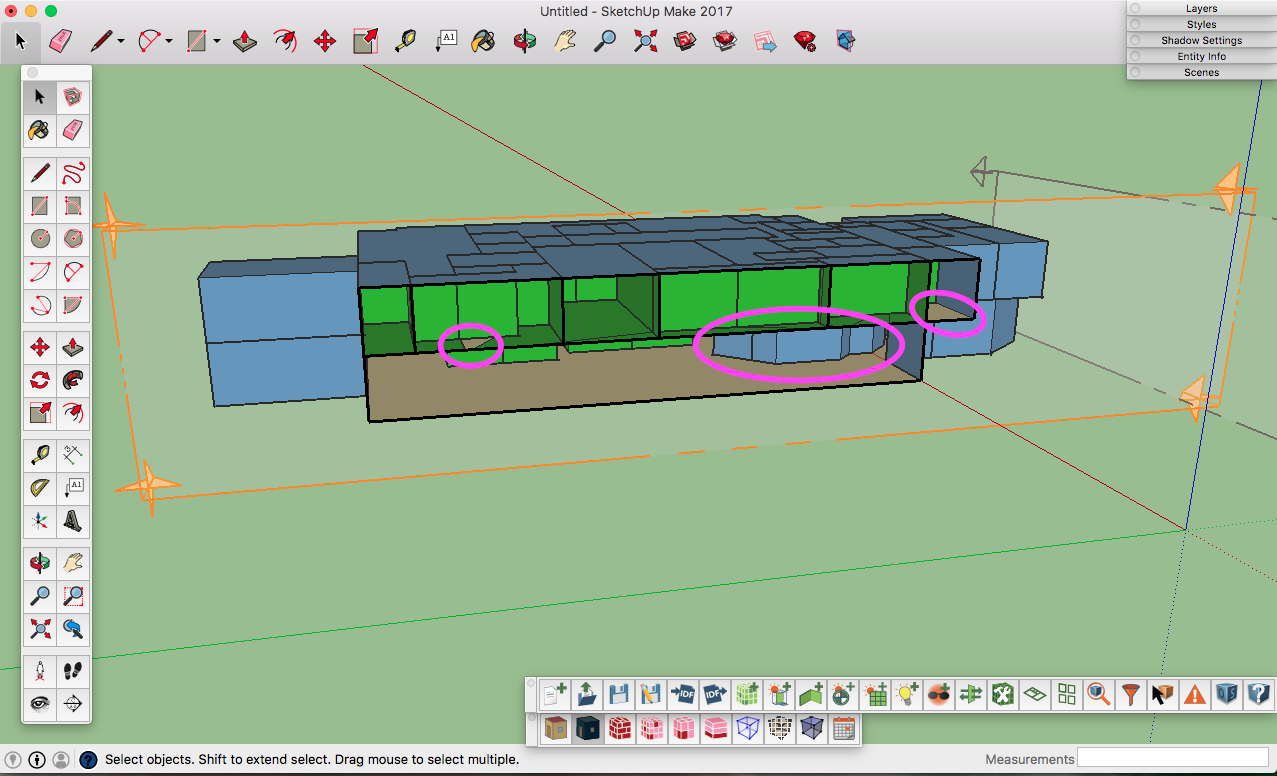
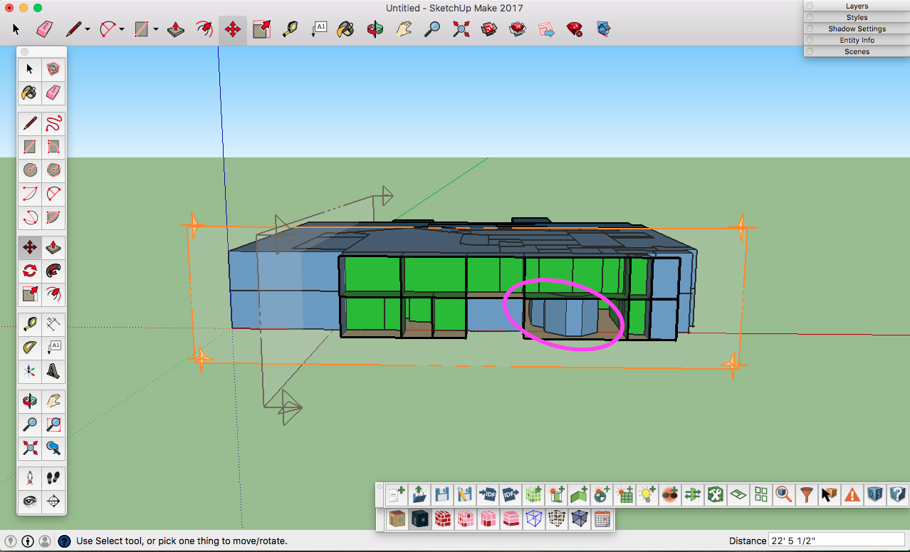
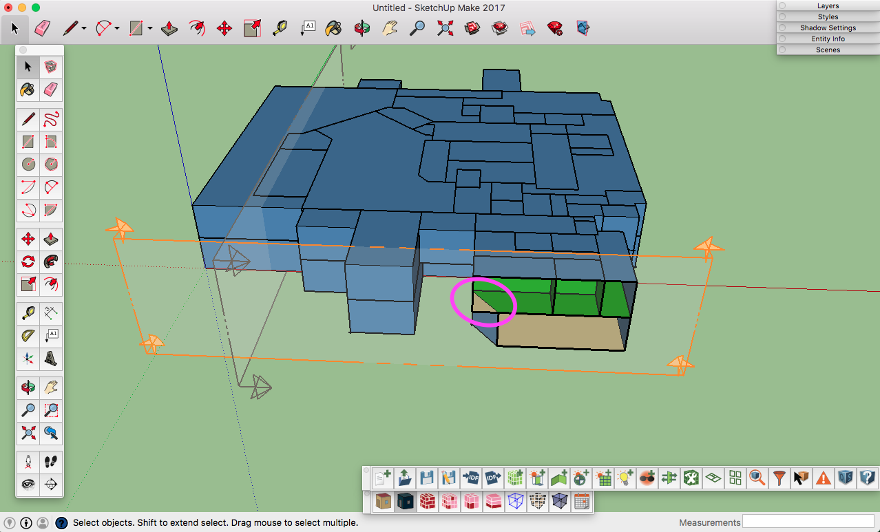
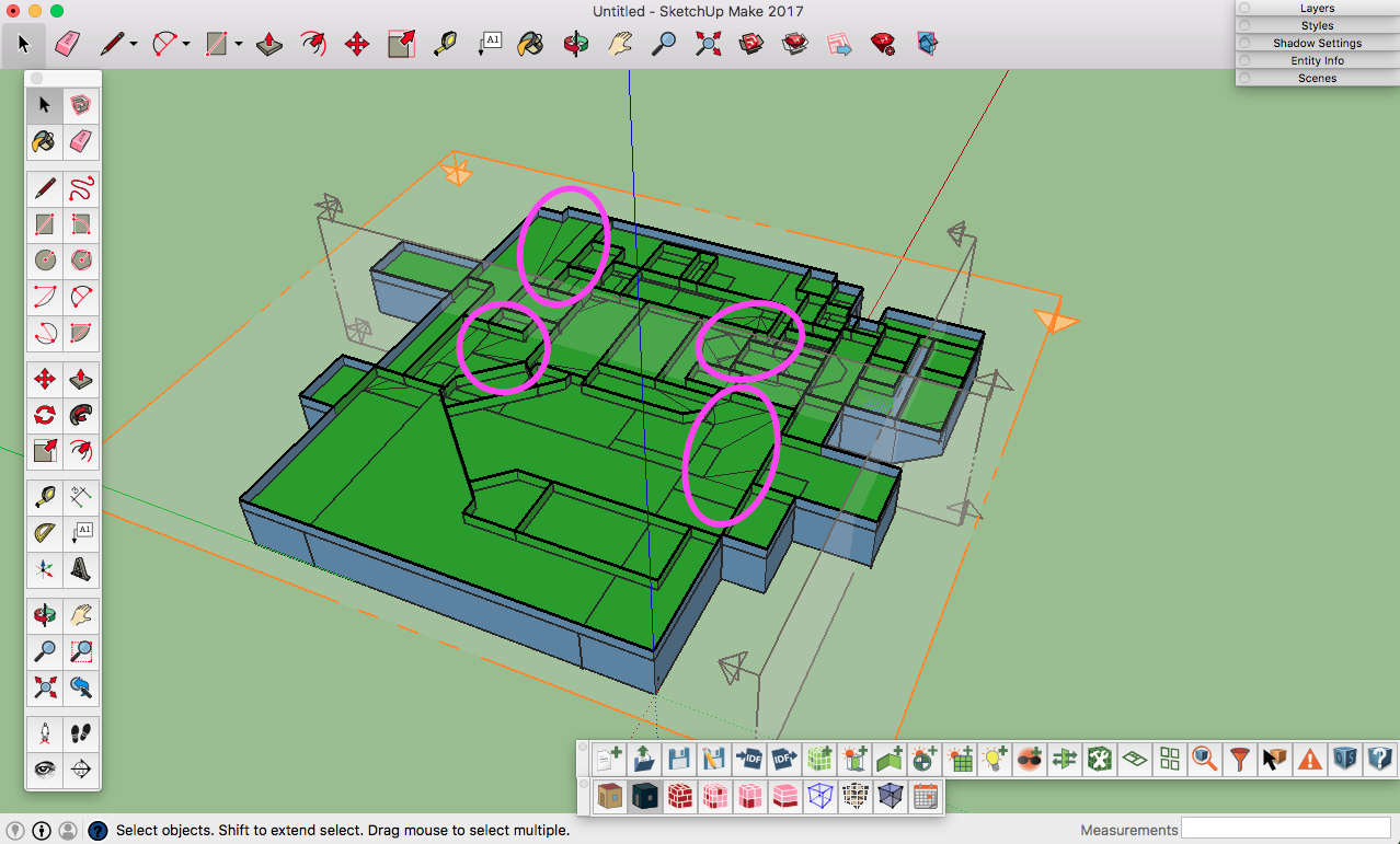
Hi, I'm modeling a 2-storey building where level 1 and level 2 have different layouts of spaces (I am using SketchUp Make 2017 and OpenStudio 2.1.0). I've created spaces with the "create spaces from diagram" tool in the plugin (to avoid snapping issues that may result from drawing each space separately with the new space tool). I've tried surface matching, but some floors and walls have incorrect boundary conditions. Reading on a previous post (https://unmethours.com/question/1687/surface-matching-with-openstudio-surface-matching-and-intersecting-measure/), I tried using the intersecting and surface matching measures in the OS app instead, and this approach resulted in fewer incorrect boundaries for surfaces; however, still some of the 2nd level floor was ground bound, and some 1st level ceiling and some interior walls were outside bound. Some examples of incorrect boundaries which are (seemingly) correctable when using the Inspector tool:
C:\fakepath\Screen Shot 2017-07-19 at 10.46.19 PM.png C:\fakepath\Screen Shot 2017-07-19 at 10.48.46 PM.png C:\fakepath\Screen Shot 2017-07-19 at 10.50.20 PM.png C:\fakepath\Screen Shot 2017-07-19 at 11.56.15 PM.png ("facets")
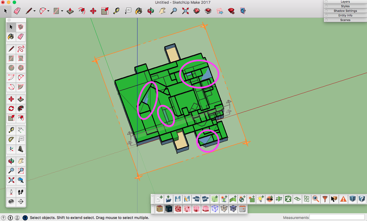
It seems like I can fix these few problems "by hand" via the "Outside Boundary Condition Object" in the Inspector, as seen on a previous post, but when I try to match an incorrectly labelled exterior wall to another interior wall, although the incorrectly labelled "exterior" surface that I am changing to an interior surface (green surface as per Render by Boundary mode) does in fact turn green, then the surface I am using for the matching sometimes itself turns blue (hinting an exterior surface), even though it still reads as having no sun or wind exposure and indicates that the 2 surfaces are matched. Because of this, I am concerned that the tool may not be correctly adjusting the boundary condition. There are also additional "facets" in the floor plan (presumably resulting from the intersecting tool because the floor layouts are not identical), which each constitute another surface, even though they are part of the same floor in a given space.
Although I don't have any errors or warnings after adjusting the boundary of several surfaces, will I run into errors as I proceed to specify the spaces, thermal zones, and HVAC systems, etc. because of the "facets" and because the surface matching was not a "clean" surface match and I had to make adjustments to boundary condition objects of some of the surfaces "by hand" via the Inspector tool? Is it possible to avoid these intersecting and surface-matching issues? Is each surface drawn double-sided by default, such that even if surface-matching is performed correctly, one side of a wall can still have exterior exposure while the other side is interior? Any suggestions for improvement would be greatly appreciated! Thanks so much!
I am adding the following, after following the suggestions in @rsunnam's answer:
Thank you @rsunnam. I appreciate your suggestions and have spent considerable time redrawing my two floor plans, taking great care to snap to end points and ensure lines are drawn in the same plane. After having done this, I then surface-matched each floor plan in a separate .osm (in the plugin), and when viewing in render by boundary mode the interior walls were all green and all surfaces were as they should be. However, when the two different floor plans are extruded in the same .osm file and then surface-matched in the plugin, although all interior walls are green and all exterior walls and roof blue, still the entire ceiling of the first floor is outside bound and the entire floor of second floor shows as ground in the Inspector. And there are still those pesky "facets" that show up when I intersect the model.
Thus, I tend to think that the problem lies with the fact that the two floor plans are not identical. The intersection and surface-matching tools present no problems when I copy/paste to stack identical floors. But surely OS has the capability to accommodate different floor plans at different levels as would be the case in such a retrofit project ... OS is so powerful and useful, so I'm convinced the problem must be on my end!
Maybe my workflow is flawed? I drew the first floor with sketchup tools in a separate .skp file, I then copy/pasted the floor plan as a group into a new .skp file (which is not linked to the .osm I am drawing in, since I have found that linking an .osm to a .skp file via sequentially saving the .osm and then the .skp tends to yield errors). Then, there in the new, unlinked .skp file I exploded the group so that I'm always working top-level and used the "create space diagram" tool to extrude the diagram to the desired height of the energy model. I then used the same procedure for the second floor, stacked right on top of the first floor.
With minimal success using the surface-matching tool in the plugin, I then tried running the surface-matching measure (with intersection) through the OS app, which proved slightly more successful ... using the measure, the first floor had all correct boundary surfaces, but the second floor was not as obedient ...
C:\fakepath\Screen Shot 2017-07-20 at 11.27.56 PM.png
... the "facets" still show up and some surfaces are not drawn, giving errors like:
"Error: Surface 923
Cannot compute outward normal.
This error cannot be automatically fixed. The surface will not be drawn."
(This is clearly an intersecting issue, but I don't think it's possible to get around the intersecting part of the workflow; as I see it, intersecting the model is essential in order to tell OS that I have a 2-storey building with different floor plates.)
When I manually fix the problem surfaces, either by matching using the Inspector, or deleting in a text editor and then redrawing in the plugin, the same surfaces show up again with wrong boundaries and give the same errors. In further trying to troubleshoot and digging a bit deeper, I have noticed that some spaces on the second floor have 2 surfaces in the same location: one surface is a floor with surface boundary, the other is a roof/ceiling with outside boundary. However, I had assumed that when the intersection/surface-match measure is run, that the ceiling surface of the first level would be intersected with the floor surfaces of the second level, resulting in a single surface that has an (indoor) surface boundary. Is this correct?
Running the simulation of the model as is failed:
Initializing workflow.
Processing OpenStudio Measures.
Translating the OpenStudio Model to EnergyPlus.
Processing EnergyPlus Measures.
Starting Simulation.
EnergyPlus Starting
EnergyPlus, Version 8.7.0-78a111df4a, YMD=2017.07.20 23:56
Processing Data Dictionary
Processing Input File
Initializing Simulation
Reporting Surfaces
Beginning Primary Simulation
Computing Life Cycle Costs and Reporting
Writing final SQL reports
**FATAL:Error condition occurred. Previous Severe Errors cause termination.
EnergyPlus Run Time=00hr 00min 0.64sec
Failed.
... Would you have any more suggestions? I would greatly appreciate it! Thanks so much!


