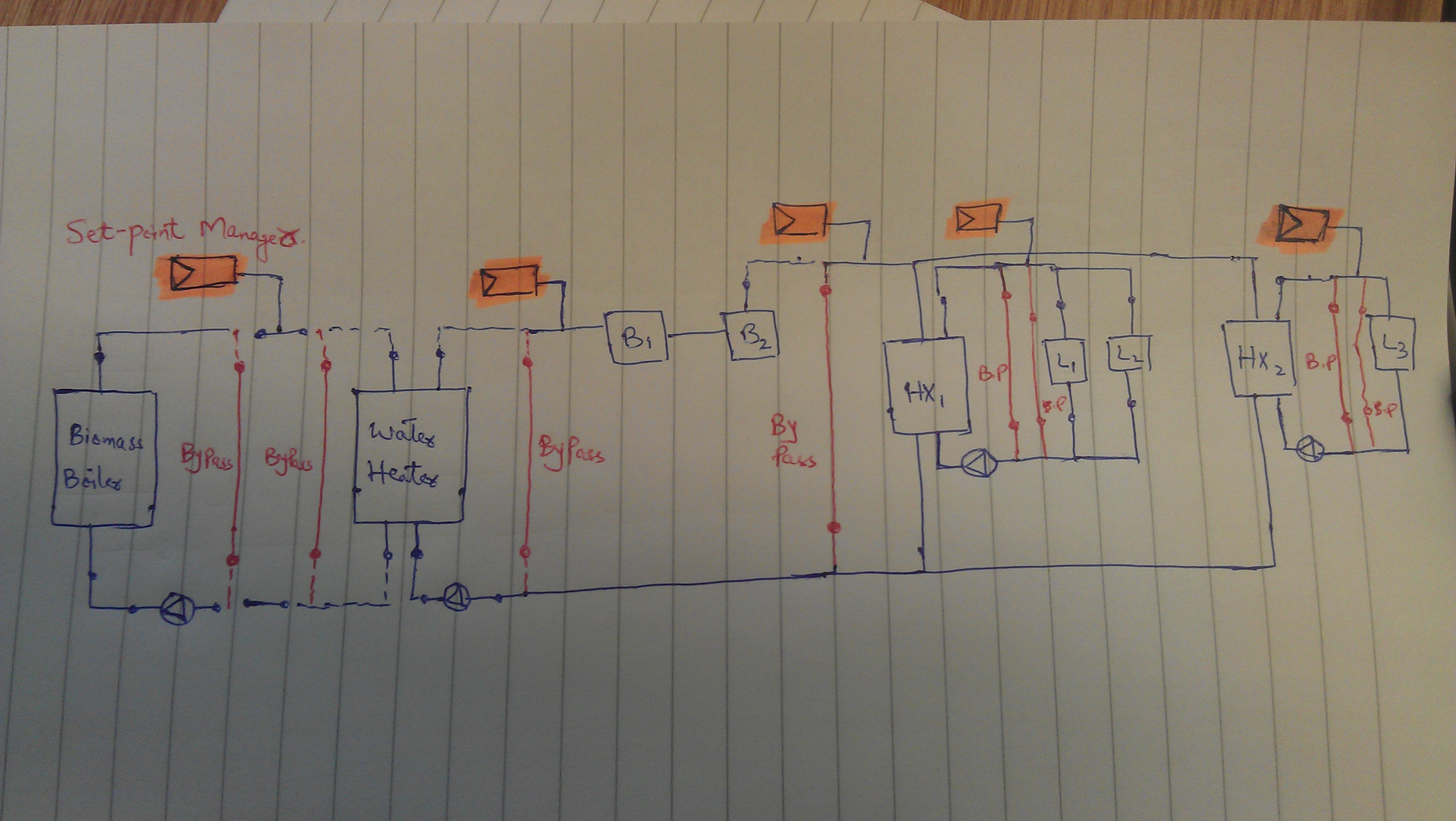
I am modelling a system with biomass boiler, water heater, Gas boilers (B1, B2 in figure below) and two heat exchangers. I have modeled 4 Loops as below;
Loops
- Biomass Loop -- biomass boiler on supply side and Water heater on demand side.
- Hot water Loop -- Water heater, B1 and B2 on supply side (sequential load distribution) and Heat exchangers on demand side.
- Heat exchanger 1 Loop -- Heat exchanger (HX1) on supply side and Loads (L1 and L2) on demand side.
- Heat exchanger 2 Loop -- Heat exchanger (HX2) on supply side and Load (L3) on demand side.
The reason for having two Heat exchangers is to divide the loop into two circuits; constant temperature (serving AHUs) and variable temperature (serving radiant panels). I have few question regarding this setup. Is the set-up in correct configuration i.e. requirement of loops, number of pumps and their position? Also, number of bypass pipes and their position is correct or not?
I have used SetpointManager:Scheduled Set-point managers and was wondering if their position is correct or not? Also, how can I set-up managers to provide variable and constant temperature? One option could be to model variable pump in one of the Heat Exchanger's circuit and constant pump in the other. Any ideas?