Question-and-Answer Resource for the Building Energy Modeling Community
Get started with the Help page
Ask Your Question
4

Correct Location of Bypass pipe and set-point managers

asked 2015-08-27 09:33:25 -0500

Waseem's avatar

updated 2015-11-12 15:39:15 -0500

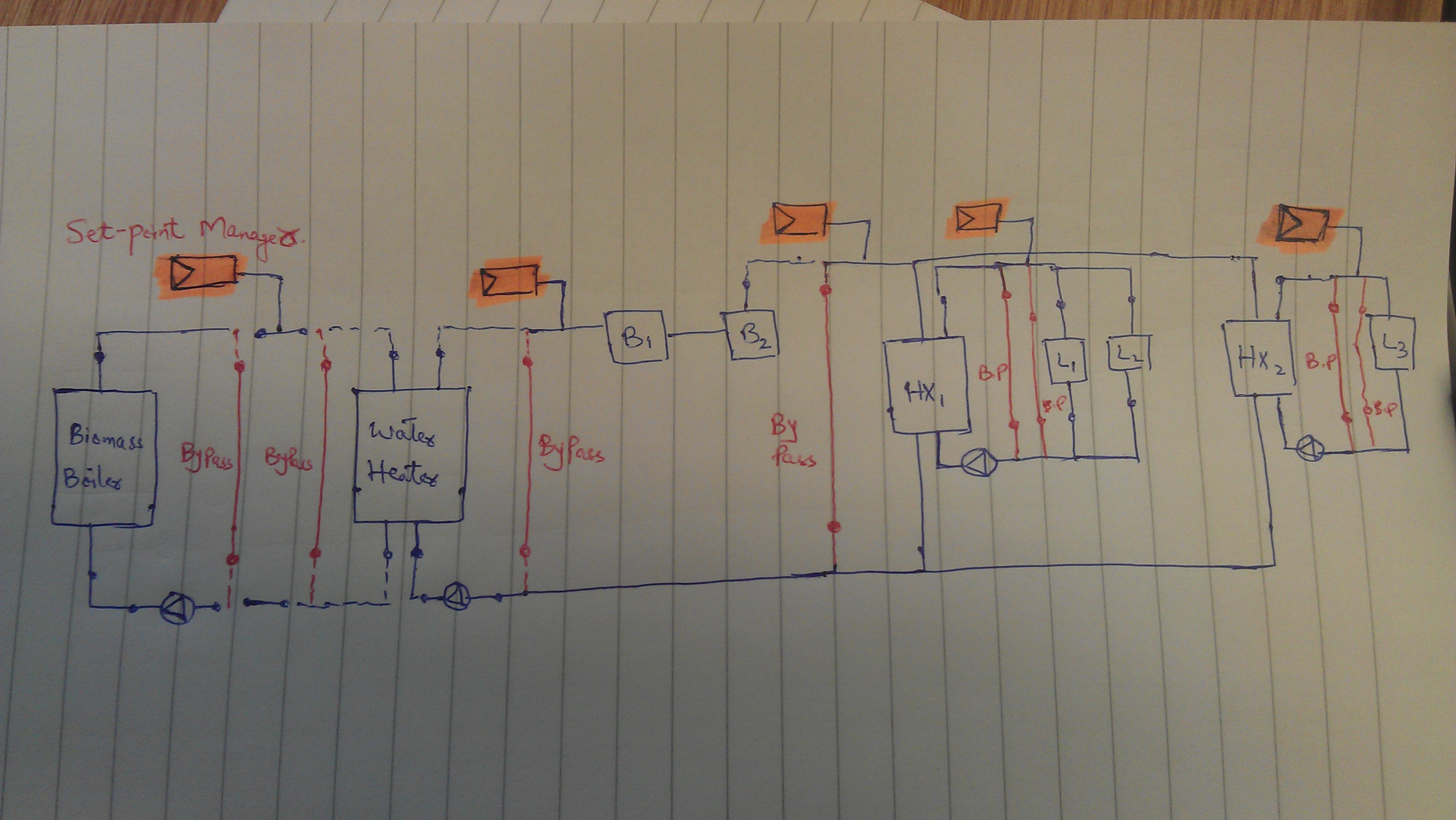
I am modelling a system with biomass boiler, water heater, Gas boilers (B1, B2 in figure below) and two heat exchangers. I have modeled 4 Loops as below;

Loops

  1. Biomass Loop -- biomass boiler on supply side and Water heater on demand side.
  2. Hot water Loop -- Water heater, B1 and B2 on supply side (sequential load distribution) and Heat exchangers on demand side.
  3. Heat exchanger 1 Loop -- Heat exchanger (HX1) on supply side and Loads (L1 and L2) on demand side.
  4. Heat exchanger 2 Loop -- Heat exchanger (HX2) on supply side and Load (L3) on demand side.

The reason for having two Heat exchangers is to divide the loop into two circuits; constant temperature (serving AHUs) and variable temperature (serving radiant panels). I have few question regarding this setup. Is the set-up in correct configuration i.e. requirement of loops, number of pumps and their position? Also, number of bypass pipes and their position is correct or not?

I have used SetpointManager:Scheduled Set-point managers and was wondering if their position is correct or not? Also, how can I set-up managers to provide variable and constant temperature? One option could be to model variable pump in one of the Heat Exchanger's circuit and constant pump in the other. Any ideas?

EnergyPlus schematic

edit retag flag offensive close merge delete

Comments

Did you figure out how to do constant flow, variable temperature plant loops?

Julien Marrec's avatar Julien Marrec  ( 2015-09-21 03:22:21 -0500 )edit

@Julien Marrec: I think it can be done by using constant flow and variable flow pumps, what you recommend?

Waseem's avatar Waseem  ( 2015-09-21 04:40:07 -0500 )edit

I think you need:

  • a constant flow pump,
  • a boiler with Flow Mode ConstantFlow
  • A plant loop with SetpointManager:DualSetpoint on the supply outlet, and a Plant Loop Demand Calculation Scheme to DualSetpointDeadband (otherwise you get constant temperature at the supply side outlet, right in the middle of the DualSetpoint's Low and High Setpoints)
Julien Marrec's avatar Julien Marrec  ( 2015-09-21 06:00:39 -0500 )edit

1 Answer

Sort by ยป oldest newest most voted
2

answered 2015-08-27 10:03:07 -0500

updated 2015-08-27 10:15:27 -0500

  • Typically, the setpoint managers belong on the supply side outlet node.
  • The bypass branches should be in parallel with your supply side equipment, and your demand side equipment.
  • Your boilers should either be on the same branch as your water heater in series, or on parallel branches to your water heater (and your bypass branch).

In parallel:

image description

In series:

image description

edit flag offensive delete link more

Comments

@Neal Kruis: This means first two points are correctly modeled in my schematic, as my set-points are on the supply side outlet node and bypass branches are parallel to my supply and demand sides equipment. I only have to move my boilers (B1 and B2) so that they can be on same branch as my water heater and then these will be parallel to bypass branch and demand side equipment (which in this case are heat exchangers), am I right?

Waseem's avatar Waseem  ( 2015-08-27 10:08:26 -0500 )edit

@Waseem I think we're on the same page. I added schematics to illustrate the two options.

Neal Kruis's avatar Neal Kruis  ( 2015-08-27 10:16:38 -0500 )edit

@Neal Kruis: I Agree, Thanks :)

Waseem's avatar Waseem  ( 2015-08-27 10:25:02 -0500 )edit

Your Answer

Please start posting anonymously - your entry will be published after you log in or create a new account.

Add Answer

Training Workshops

Careers

Question Tools

1 follower

Stats

Asked: 2015-08-27 09:33:25 -0500

Seen: 281 times

Last updated: Aug 27 '15