Question-and-Answer Resource for the Building Energy Modeling Community
Get started with the Help page
Ask Your Question
5

Fan:SystemModel power curve does not work

asked 2022-03-04 07:46:49 -0600

Keigo's avatar

updated 2022-10-12 20:54:52 -0600

I have two problems.

  • Fan Electric Power of Fan:SystemModel is constant although the fan airflow is variable.
  • Fan:SystemModel is ON when Availability Schedule is 0 during midnight (1am to 6am).

This post is related to my previous question. I have modelled PAU+AHU with AirLoopHVAC:DedicatedOutdoorAirSystem. As you may know, only Fan:SystemModel is allowed for modelling AirLoopHVAC:DedicatedOutdoorAirSystem. Fan:VariableVolume is not allowed. I have modelled PAU with DCV by CO2 concentration, so the outdoor airflow rate is variable, but Fan Electric Power is constant. I don't know why. Besides, Availability Schedule makes the outdoor airflow rate 0 during midnight of weekdays, but the fan consumes electric power for 24 hours. Please find the charts below.
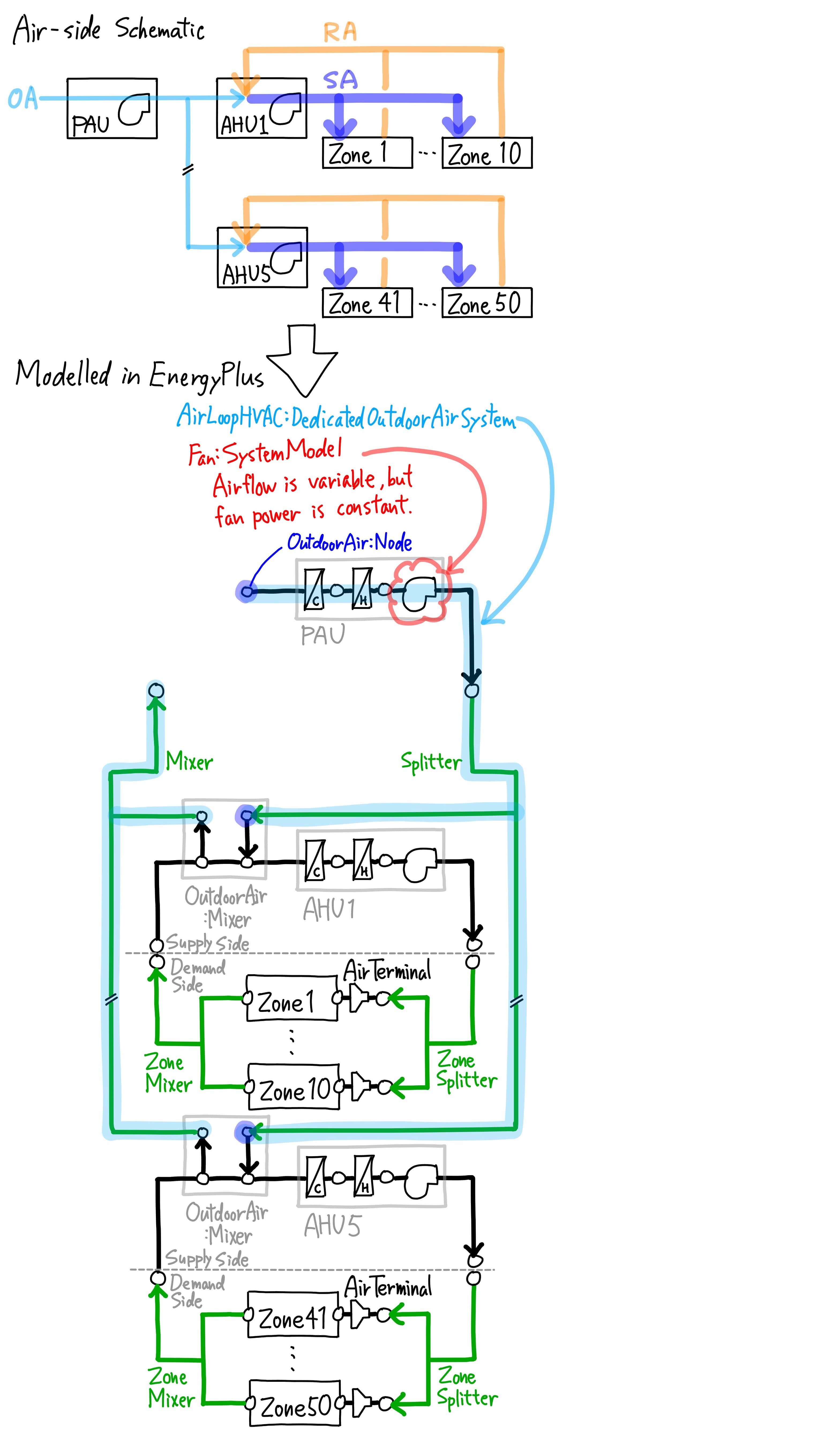
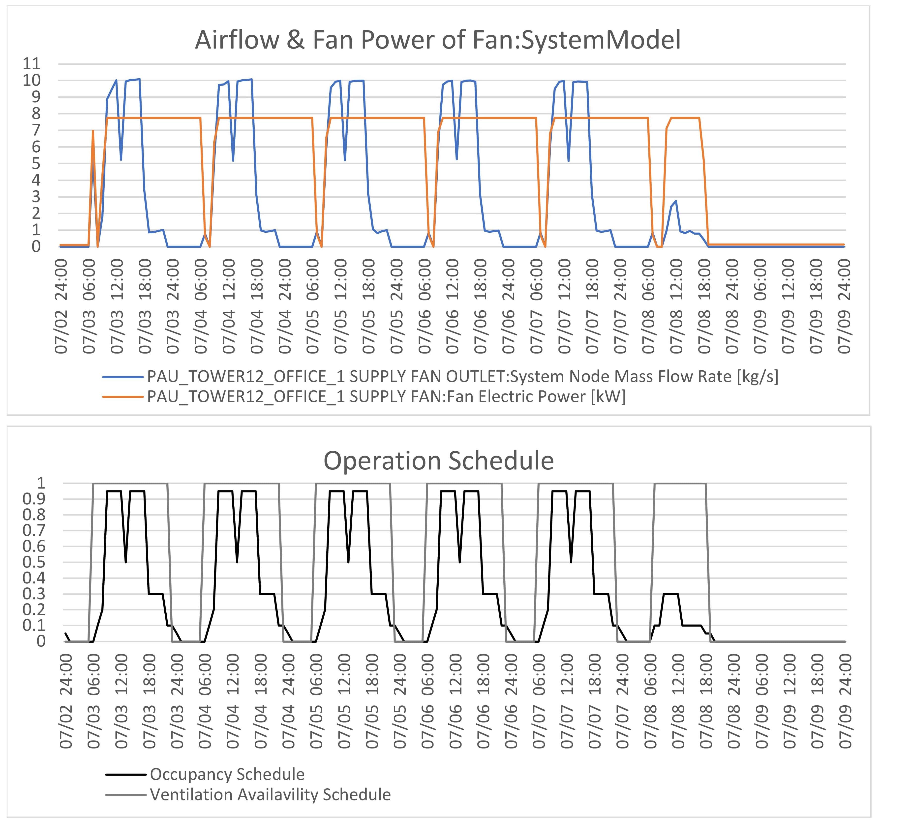
image description

image description

My Fan:SystemModel input is as follows. Is there anything wrong with it?

Fan:SystemModel,
    PAU_Tower12_Office_1 Supply Fan,  !- Name
    LEED_V4_OFFICE_VENTILATION,  !- Availability Schedule Name
    PAU_Tower12_Office_1 Cooling Coil Outlet,  !- Air Inlet Node Name
    PAU_Tower12_Office_1 Supply Fan Outlet,  !- Air Outlet Node Name
    autosize,                !- Design Maximum Air Flow Rate {m3/s}
    Continuous,              !- Speed Control Method
    0.2,                     !- Electric Power Minimum Flow Rate Fraction
    1200,                    !- Design Pressure Rise {Pa}
    0.9,                     !- Motor Efficiency
    1,                       !- Motor In Air Stream Fraction
    autosize,                !- Design Electric Power Consumption {W}
    TotalEfficiencyAndPressure,  !- Design Power Sizing Method
    ,                        !- Electric Power Per Unit Flow Rate {W/(m3/s)}
    ,                        !- Electric Power Per Unit Flow Rate Per Unit Pressure {W/((m3/s)-Pa)}
    0.7,                     !- Fan Total Efficiency
    ASHRAE90.1 TABLE G3.1.3.15 Fan Power Curve,  !- Electric Power Function of Flow Fraction Curve Name
    ,                        !- Night Ventilation Mode Pressure Rise {Pa}
    ,                        !- Night Ventilation Mode Flow Fraction
    ,                        !- Motor Loss Zone Name
    ,                        !- Motor Loss Radiative Fraction
    General;                 !- End-Use Subcategory
    ,                        !- Number of Speeds
    ,                        !- Speed 1 Flow Fraction
    ,                        !- Speed 1 Electric Power Fraction

Fan curve input is as follows. It is based on ASHRAE90.1 TABLE G3.1.3.15. I think there should be no problem with it becuase AHUs that have been modelled with Fan:Variable and with the same coeciffients as this fan power curve have variable Fan Electric Power.

Curve:Cubic,
    ASHRAE90.1 TABLE G3.1.3.15 Fan Power Curve,  !- Name
    0.0013,                  !- Coefficient1 Constant
    0.147,                   !- Coefficient2 x
    0.9506,                  !- Coefficient3 x**2
    -0.0998,                 !- Coefficient4 x**3
    0,                       !- Minimum Value of x
    1;                       !- Maximum Value of x

AirLoopHVAC:DedicatedOutdoorAirSystem and Fan:SystemModel use the same Availability Schedule, so Fan:SystemModel should be OFF during midnight, but it isn't.

AirLoopHVAC:DedicatedOutdoorAirSystem,
    PAU_Tower12_Office_1,    !- Name
    PAU_Tower12_Office_1 OA System,  !- AirLoopHVAC:OutdoorAirSystem Name
    LEED_V4_OFFICE_VENTILATION,  !- Availability Schedule Name
    PAU_Tower12_Office_1 Zone Mixer,  !- AirLoopHVAC:Mixer Name
    PAU_Tower12_Office_1 Zone Splitter,  !- AirLoopHVAC:Splitter Name
    4.5,                     !- Preheat Design Temperature {C}
    0.004,                   !- Preheat Design Humidity Ratio {kgWater/kgDryAir}
    17.5,                    !- Precool Design Temperature {C}
    0.012,                   !- Precool Design Humidity Ratio {kgWater/kgDryAir}
    5,                       !- Number of AirLoopHVAC
    VAV_TOWER12_28F,         !- AirLoopHVAC 1 Name
    VAV_TOWER12_26-27F,      !- AirLoopHVAC 2 Name
    VAV_TOWER12_25F,         !- AirLoopHVAC 3 Name
    VAV_TOWER12_23-24F,      !- AirLoopHVAC 4 Name
    VAV_TOWER12_22F;         !- AirLoopHVAC 5 Name

P.S.

I noticed another problem of AirLoopHVAC:DedicatedOutdoorAirSystem. Please let me know If I should post as a separate question.

It's not about ... (more)

edit retag flag offensive close merge delete

Comments

I have a number of models with a Fan:SystemModel on a AirLoopHVAC:DedicatedOutdoorAirSystem serving AHUs with DCV, configured similar to yours, and have confirmed that the fan power does modulate with airflow rate (E+ v9.6). I find it curious that you're reporting 'Fan Electric Power', which is not an output for that object (rather, 'Fan Electricity Rate'). Are you post-processing the output data, and could that be a source of the odd results?

ericringold's avatar ericringold  ( 2022-03-04 14:46:51 -0600 )edit

Another idea is to leave the fan availability as 'Always On', and let the AHU OA controllers determine when it operates. IDK why that would affect reported fan power, but you never know with new features.

ericringold's avatar ericringold  ( 2022-03-04 14:52:28 -0600 )edit

@Eric Ringold, thank you for your comments. About Output:Variable, I'm using EnrgyPlus v9.2.0 and Fan Electric Power is the output of Fan:SystemModel object. There is no Output:Variable of Fan Electricity Rate in EnergyPlus v9.2.0. As a post-process, I have multuplied Fan Electric Power by 1000 and changed the unit from [W] to [kW] in order to make the chart easier to read, but I'm sure it is notthing to do with the odd results.

Keigo's avatar Keigo  ( 2022-03-04 18:25:27 -0600 )edit
1

Very nice presentation of the problem. Please provide the input file so that the reason for this can be identified.

rraustad's avatar rraustad  ( 2022-03-04 19:04:33 -0600 )edit
1

Please find my idf file and simulation result here. The building has three AirLoopHVAC:DedicatedOutdoorAirSystems and three Fan:SystemModels for the DOASs. PAU_Tower12_Office_1 Supply Fan is one of them, and all three Fan:SystemModels for DOAS are in the same situation.

By the way, I noticed that Output:Variable: Fan Air Mass Flow Rate and System Node Mass Flow Rate at Nodes before and after the fan are different. I don't know which is correct.

Keigo's avatar Keigo  ( 2022-03-06 05:51:38 -0600 )edit

2 Answers

Sort by ยป oldest newest most voted
3

answered 2022-03-15 11:41:59 -0600

Keigo's avatar

updated 2022-03-29 08:27:29 -0600

Let me add to @rraustad 's answer. His answer was a great clue. My conclusion is that AirLoopHVAC:DedicatedOutdoorAirSystem does not correctly autosize fan flow rate as well as coil capacity.

The flow rate fraction of Fan:SystemModel was always below Electric Power Minimum Flow Rate Fraction of 0.2, which resulted in the constant fan power. There are two possible causes for such a low flow fraction rate: Extremely low indoor CO2 concentration or Extremely high fan design air flow rate. My DCV setting is reasonable. 400ppm for outdoor CO2 concentration, 1000ppm for indoor threshould and 0.111person/m2 for office occupant density. Then, the cause is the latter.

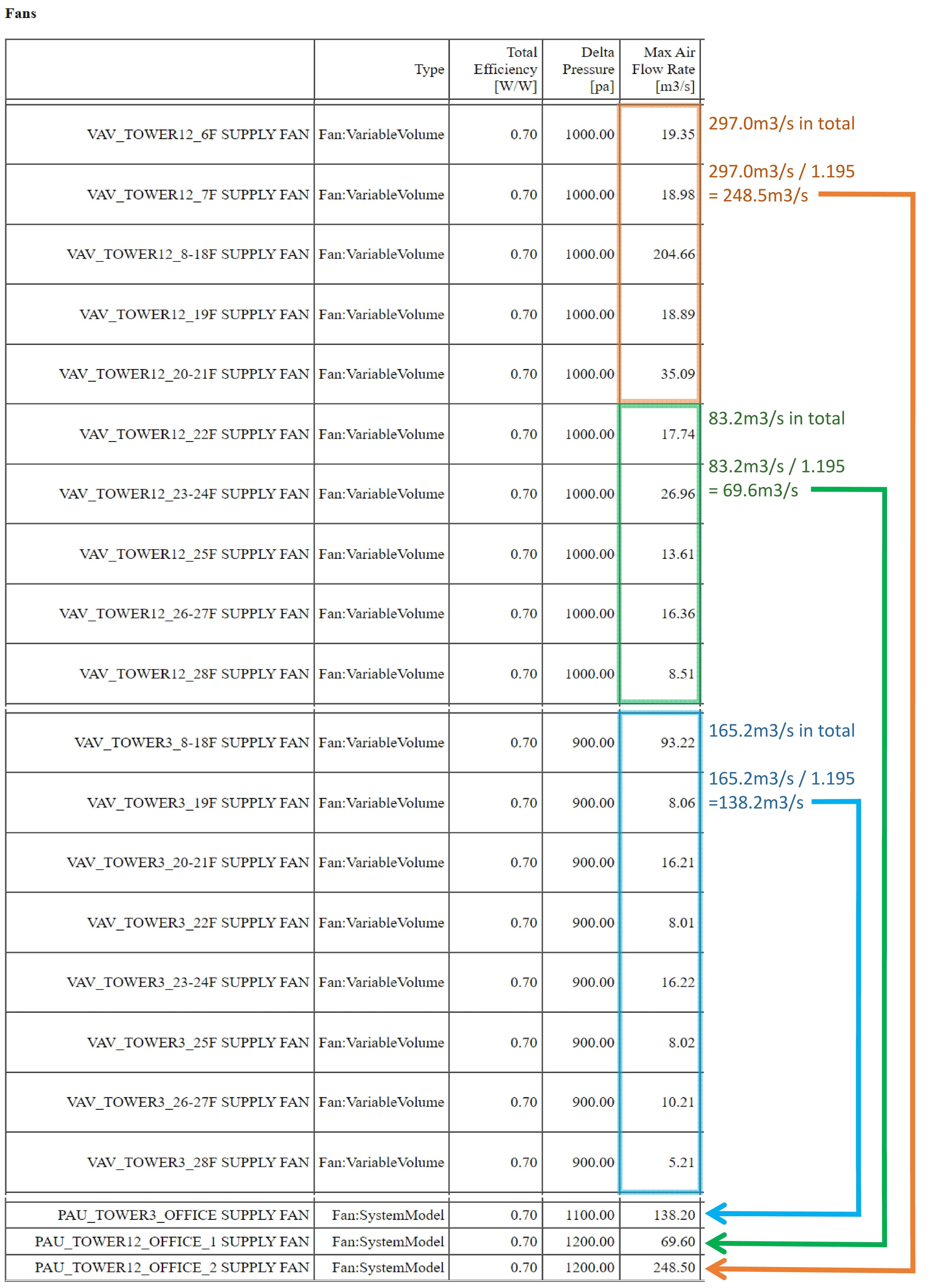
I have no idea why, but PAU's Fan:SystemModel design air flow rate is autosized by dividing the total supply air flow rate (not the total outoor air flow rate) of the connected AHUs by approximately 1.195. The following sizing summary table is an excerpt from the html file.

image description

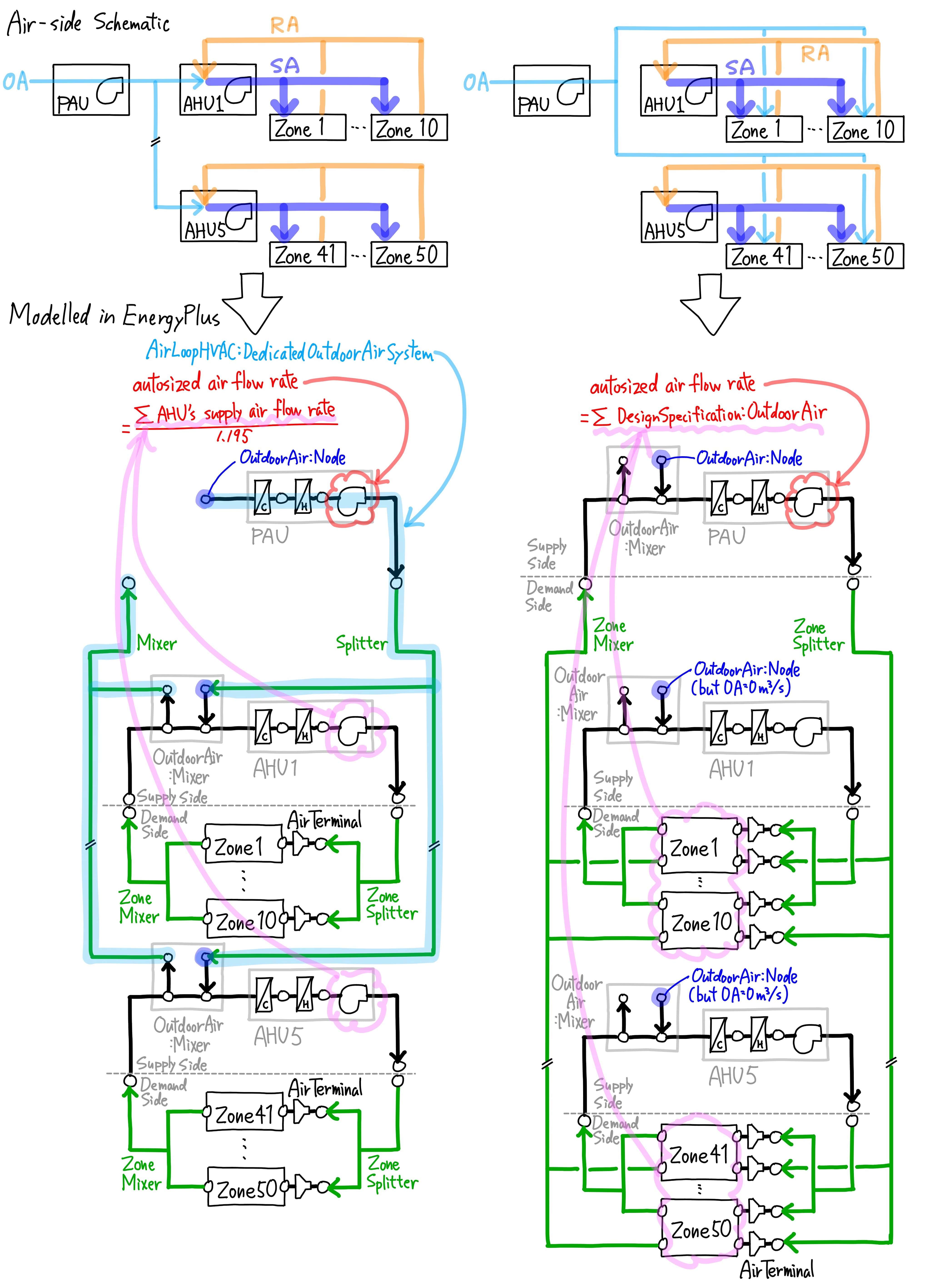
My expectation for AirLoopHVAC:DedicatedOutdoorAirSystem was that it would autosize the design PAU air flow rate by the sum of the required outdoor air flow rate for each zone defined by DesignSpecification:OutdoorAir, but in reality it was completely different. The above autosizing calculation is not appropriate at all.

I have another energy model that PAUs supply outdoor air not to AHUs but directly to each zone, so I know the original correct PAU air flow rate. PAU air flow rate with AirLoopHVAC:DedicatedOutdoorAirSystem was 7 to 10 times larger than the original correct PAU air flow rate.

image description


Just minor updates. I replaced my idf files and the above schematic. The simulation result has not changed.

I found that Inlet Node Name of AirLoopHVAC:Splitter did not match Air Outlet Node Name of Fan:SystemModel although there was no node connection error. Unlike AirloopHVAC, AirLoopHVAC:DedicatedOutdoorAirSystem has no concept of "Supply Side" and "Demand Side", so all Nodes are connected.

edit flag offensive delete link more

Comments

This is another interesting find that I will take a look at. Thanks @Keigo for laying out the facts used for sizing DOAS systems. Typically a DOAS system will provide all the supply air (i.e., 100% OA), but when a DOAS provides OA to multiple air systems, the total amount of OA may not represent the total supply air flow. This is something that the original developer may not have considered.

rraustad's avatar rraustad  ( 2022-03-15 11:58:41 -0600 )edit
2

answered 2022-03-11 09:25:21 -0600

updated 2022-03-12 16:48:27 -0600

I ran your V9.6 file in the lastest EnergyPlus code and found a bug in the program. If there are multiple AirLoopHVAC:DedicatedOutdoorAirSystem objects then only the first object finds the correct outdoor air conditions used for sizing. I posted a new issue at https://github.com/NREL/EnergyPlus/is.... This model uses the SizingPeriod:DesignDay conditions to find the outdoor weather.

In the fan model the Electric Power Minimum Flow Rate Fraction = 0.2. At flow fractions below 0.2 the fan power will remain constant. At 0 flow the power will go to 0.

Fan:SystemModel,
  PAU_Tower12_Office_1 Supply Fan,  !- Name
  LEED_V4_OFFICE_VENTILATION,  !- Availability Schedule Name
  PAU_Tower12_Office_1 Cooling Coil Outlet,  !- Air Inlet Node Name
  PAU_Tower12_Office_1 Supply Fan Outlet,  !- Air Outlet Node Name
  autosize,                !- Design Maximum Air Flow Rate {m3/s}
  Continuous,              !- Speed Control Method
  0.2,                     !- Electric Power Minimum Flow Rate Fraction
  1200,                    !- Design Pressure Rise {Pa}
  0.9,                     !- Motor Efficiency
  1,                       !- Motor In Air Stream Fraction

image description

edit flag offensive delete link more

Comments

Thank you for finding the bug. This is an answer to my P.S.

What about my first questions: weird fan power and fan schedule? Are they also caused by this bug? Or is there another cause?

Keigo's avatar Keigo  ( 2022-03-11 14:31:48 -0600 )edit

I will look at the fan power issue next.

rraustad's avatar rraustad  ( 2022-03-11 15:18:17 -0600 )edit

@rraustad maybe related to your answer in this post (fan flow below minimum flow fraction, so fan electricity rate is constant)?

Aaron Boranian's avatar Aaron Boranian  ( 2022-03-12 12:24:45 -0600 )edit

Hmm, that was supposed to be posed here.

rraustad's avatar rraustad  ( 2022-03-12 16:46:26 -0600 )edit

Your Answer

Please start posting anonymously - your entry will be published after you log in or create a new account.

Add Answer

Training Workshops

Careers

Question Tools

3 followers

Stats

Asked: 2022-03-04 07:46:49 -0600

Seen: 409 times

Last updated: Mar 29 '22