Fan:SystemModel power curve does not work

I have two problems.
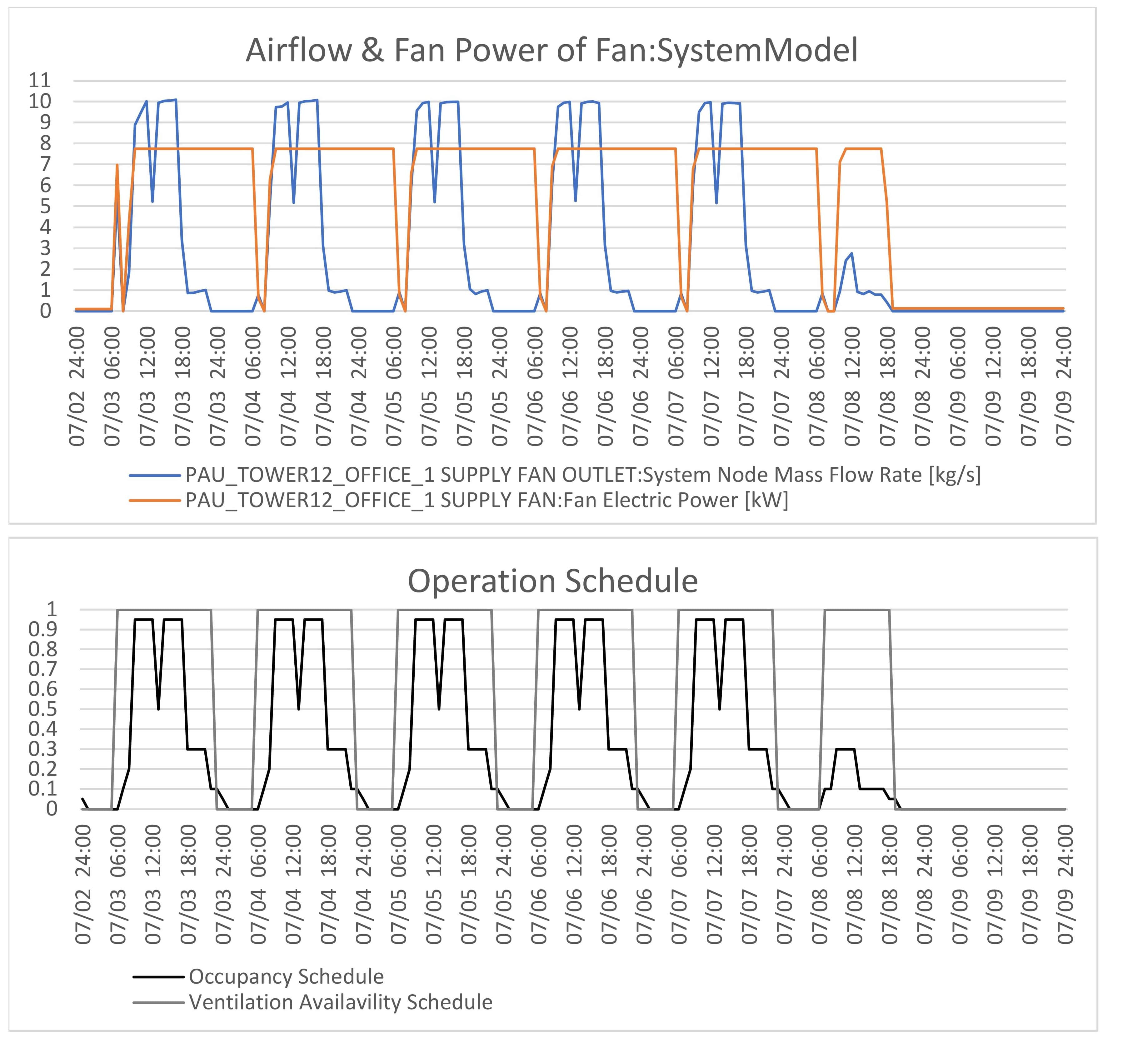
Fan Electric PowerofFan:SystemModelis constant although the fan airflow is variable.Fan:SystemModelis ON when Availability Schedule is 0 during midnight (1am to 6am).
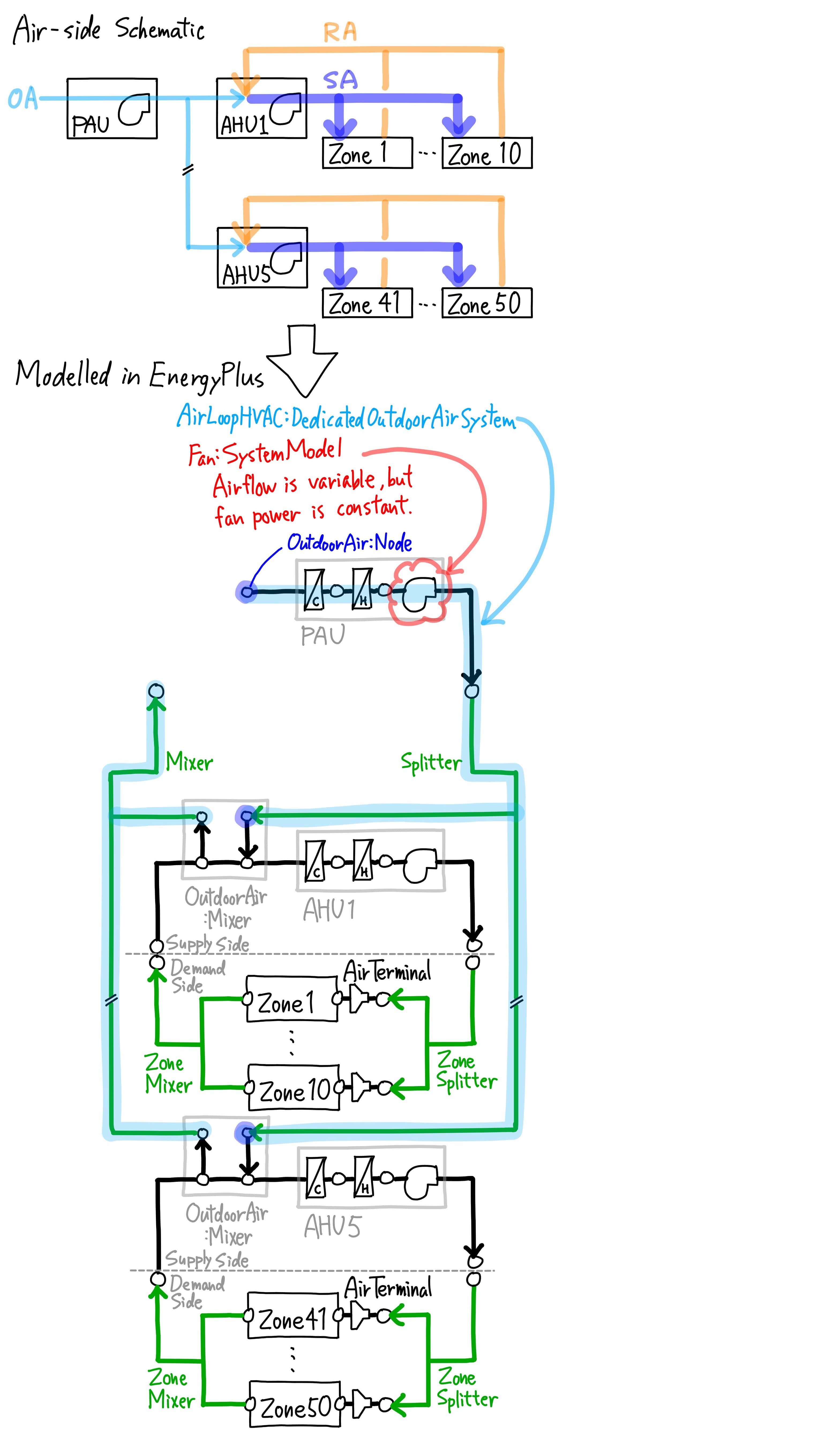
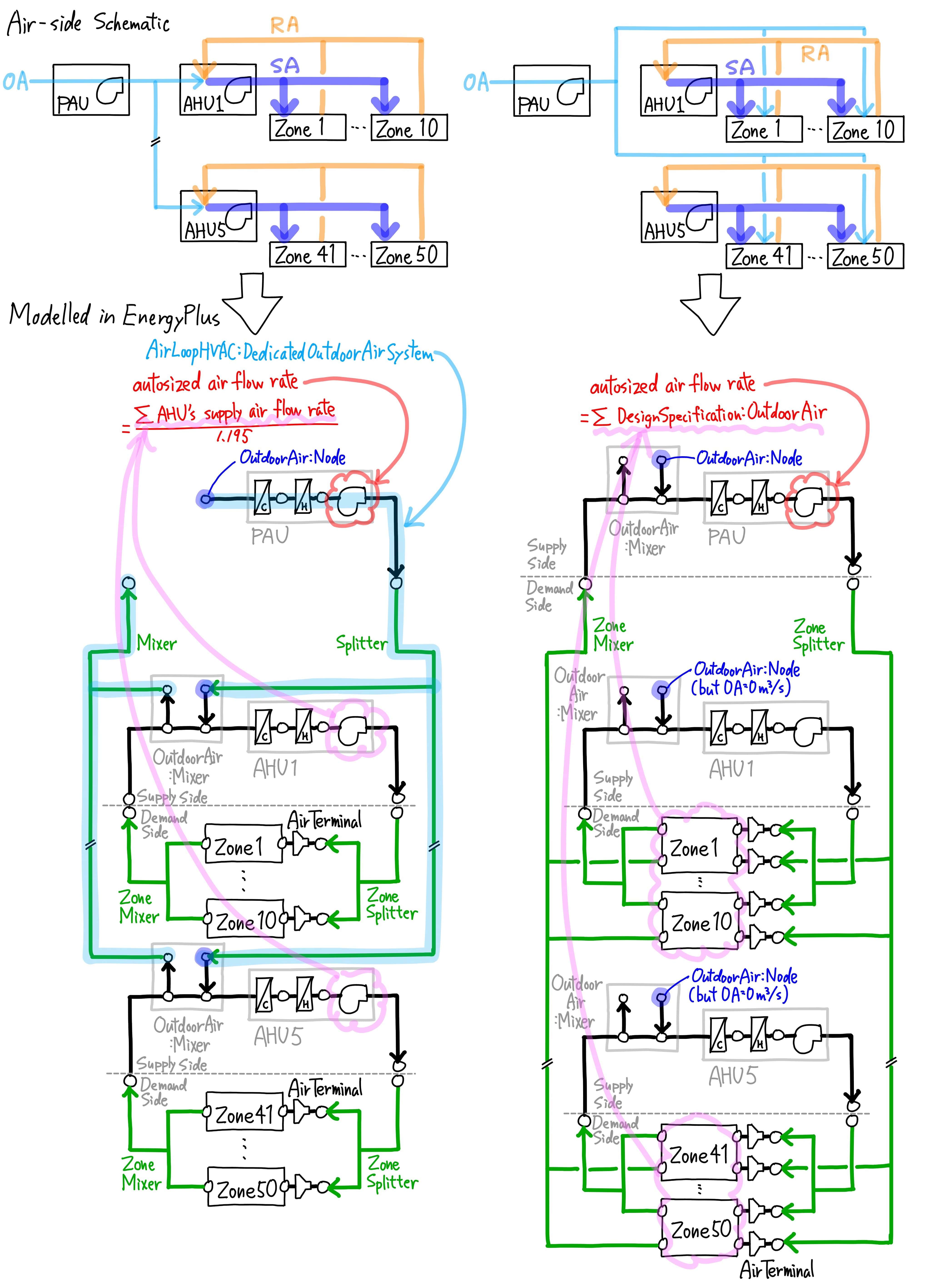
This post is related to my previous question. I have modelled PAU+AHU with AirLoopHVAC:DedicatedOutdoorAirSystem. As you may know, only Fan:SystemModel is allowed for modelling AirLoopHVAC:DedicatedOutdoorAirSystem. Fan:VariableVolume is not allowed. I have modelled PAU with DCV by CO2 concentration, so the outdoor airflow rate is variable, but Fan Electric Power is constant. I don't know why. Besides, Availability Schedule makes the outdoor airflow rate 0 during midnight of weekdays, but the fan consumes electric power for 24 hours. Please find the charts below.
My Fan:SystemModel input is as follows. Is there anything wrong with it?
Fan:SystemModel,
PAU_Tower12_Office_1 Supply Fan, !- Name
LEED_V4_OFFICE_VENTILATION, !- Availability Schedule Name
PAU_Tower12_Office_1 Cooling Coil Outlet, !- Air Inlet Node Name
PAU_Tower12_Office_1 Supply Fan Outlet, !- Air Outlet Node Name
autosize, !- Design Maximum Air Flow Rate {m3/s}
Continuous, !- Speed Control Method
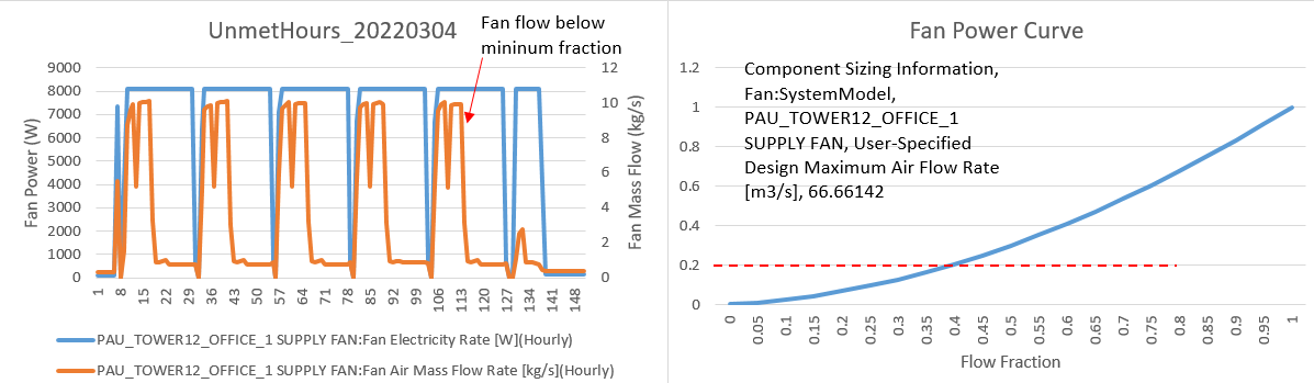
0.2, !- Electric Power Minimum Flow Rate Fraction
1200, !- Design Pressure Rise {Pa}
0.9, !- Motor Efficiency
1, !- Motor In Air Stream Fraction
autosize, !- Design Electric Power Consumption {W}
TotalEfficiencyAndPressure, !- Design Power Sizing Method
, !- Electric Power Per Unit Flow Rate {W/(m3/s)}
, !- Electric Power Per Unit Flow Rate Per Unit Pressure {W/((m3/s)-Pa)}
0.7, !- Fan Total Efficiency
ASHRAE90.1 TABLE G3.1.3.15 Fan Power Curve, !- Electric Power Function of Flow Fraction Curve Name
, !- Night Ventilation Mode Pressure Rise {Pa}
, !- Night Ventilation Mode Flow Fraction
, !- Motor Loss Zone Name
, !- Motor Loss Radiative Fraction
General; !- End-Use Subcategory
, !- Number of Speeds
, !- Speed 1 Flow Fraction
, !- Speed 1 Electric Power Fraction
Fan curve input is as follows. It is based on ASHRAE90.1 TABLE G3.1.3.15.
I think there should be no problem with it becuase AHUs that have been modelled with Fan:Variable and with the same coeciffients as this fan power curve have variable Fan Electric Power.
Curve:Cubic,
    ASHRAE90.1 TABLE G3.1.3.15 Fan Power Curve,  !- Name
    0.0013,                  !- Coefficient1 Constant
    0.147,                   !- Coefficient2 x
    0.9506,                  !- Coefficient3 x**2
    -0.0998,                 !- Coefficient4 x**3
    0,                       !- Minimum Value of x
    1;                       !- Maximum Value of x
AirLoopHVAC:DedicatedOutdoorAirSystem and Fan:SystemModel use the same Availability Schedule, so Fan:SystemModel should be OFF during midnight, but it isn't.
AirLoopHVAC:DedicatedOutdoorAirSystem,
    PAU_Tower12_Office_1,    !- Name
    PAU_Tower12_Office_1 OA System,  !- AirLoopHVAC:OutdoorAirSystem Name
    LEED_V4_OFFICE_VENTILATION,  !- Availability Schedule Name
    PAU_Tower12_Office_1 Zone Mixer,  !- AirLoopHVAC:Mixer Name
    PAU_Tower12_Office_1 Zone Splitter,  !- AirLoopHVAC:Splitter Name
    4.5,                     !- Preheat Design Temperature {C}
    0.004,                   !- Preheat Design Humidity Ratio {kgWater/kgDryAir}
    17.5,                    !- Precool Design Temperature {C}
    0.012,                   !- Precool Design Humidity Ratio {kgWater/kgDryAir}
    5,                       !- Number of AirLoopHVAC
    VAV_TOWER12_28F,         !- AirLoopHVAC 1 Name
    VAV_TOWER12_26-27F,      !- AirLoopHVAC 2 Name
    VAV_TOWER12_25F,         !- AirLoopHVAC 3 Name
    VAV_TOWER12_23-24F,      !- AirLoopHVAC 4 Name
    VAV_TOWER12_22F;         !- AirLoopHVAC 5 Name
P.S.
I noticed another problem of AirLoopHVAC:DedicatedOutdoorAirSystem. Please let me know If I should post as a separate question.
It's not about ...


I have a number of models with a Fan:SystemModel on a AirLoopHVAC:DedicatedOutdoorAirSystem serving AHUs with DCV, configured similar to yours, and have confirmed that the fan power does modulate with airflow rate (E+ v9.6). I find it curious that you're reporting 'Fan Electric Power', which is not an output for that object (rather, 'Fan Electricity Rate'). Are you post-processing the output data, and could that be a source of the odd results?
Another idea is to leave the fan availability as 'Always On', and let the AHU OA controllers determine when it operates. IDK why that would affect reported fan power, but you never know with new features.
@Eric Ringold, thank you for your comments. About
Output:Variable, I'm using EnrgyPlus v9.2.0 andFan Electric Poweris the output ofFan:SystemModelobject. There is noOutput:VariableofFan Electricity Ratein EnergyPlus v9.2.0. As a post-process, I have multupliedFan Electric Powerby 1000 and changed the unit from [W] to [kW] in order to make the chart easier to read, but I'm sure it is notthing to do with the odd results.Very nice presentation of the problem. Please provide the input file so that the reason for this can be identified.
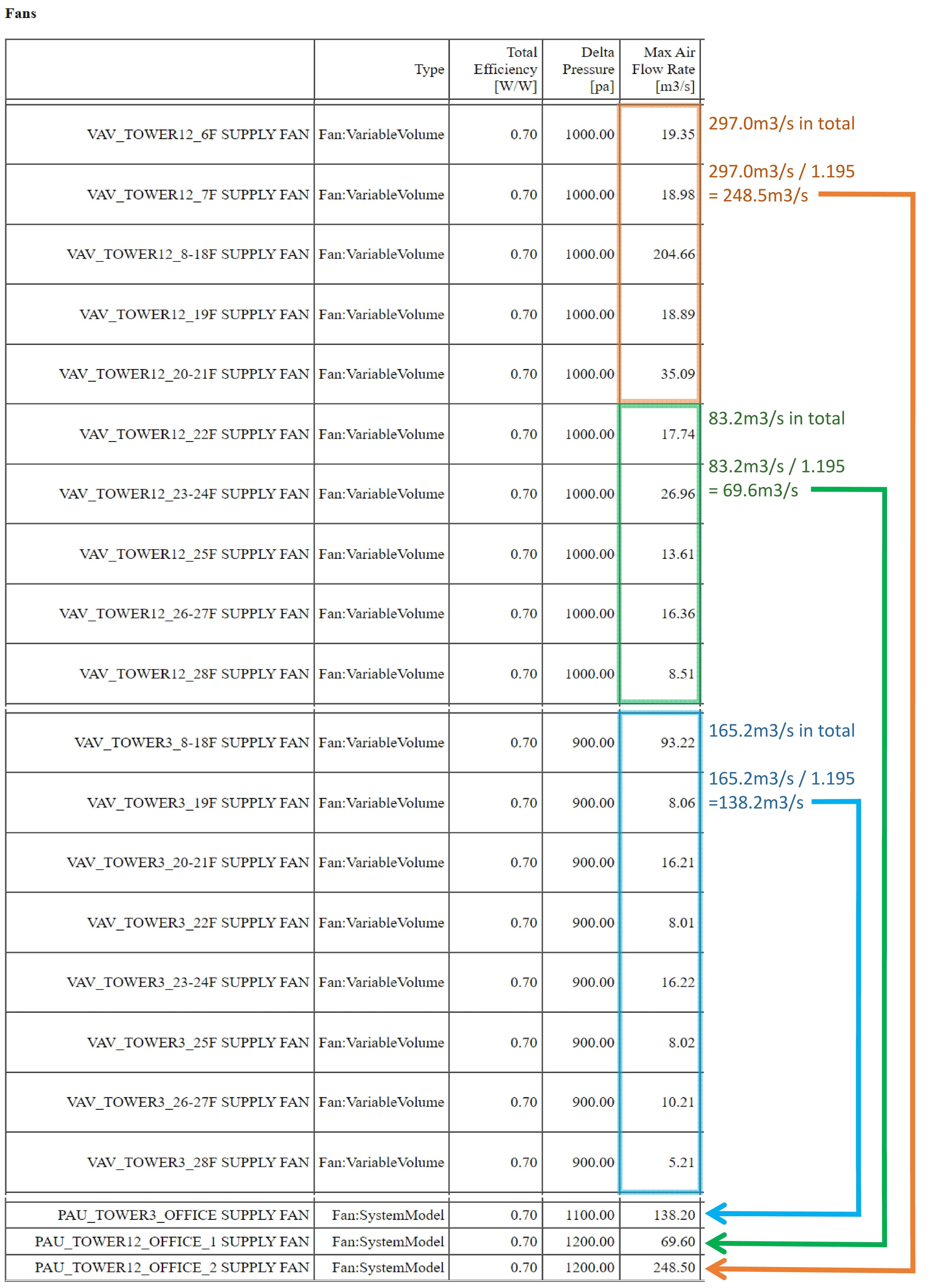
Please find my idf file and simulation result here. The building has three
AirLoopHVAC:DedicatedOutdoorAirSystems and threeFan:SystemModels for the DOASs. PAU_Tower12_Office_1 Supply Fan is one of them, and all threeFan:SystemModels for DOAS are in the same situation.By the way, I noticed that
Output:Variable:Fan Air Mass Flow RateandSystem Node Mass Flow Rateat Nodes before and after the fan are different. I don't know which is correct.