Question-and-Answer Resource for the Building Energy Modeling Community
| | 1 | initial version |
Let me add to @rraustad 's answer. His answer was a great clue. My conclusion is that AirLoopHVAC:DedicatedOutdoorAirSystem does not correctly autosize fan flow rate as well as coil capacity.
The flow rate fraction of Fan:SystemModel was always below Electric Power Minimum Flow Rate Fraction of 0.2, which resulted in the constant fan power. There are two possible causes for such a low flow fraction rate: Extremely low indoor CO2 concentration or Extremely high fan design air flow rate. My DCV setting is reasonable. 400ppm for outdoor CO2 concentration, 1000ppm for indoor threshould and 0.111person/m2 for office occupant density. Then, the cause is the latter.
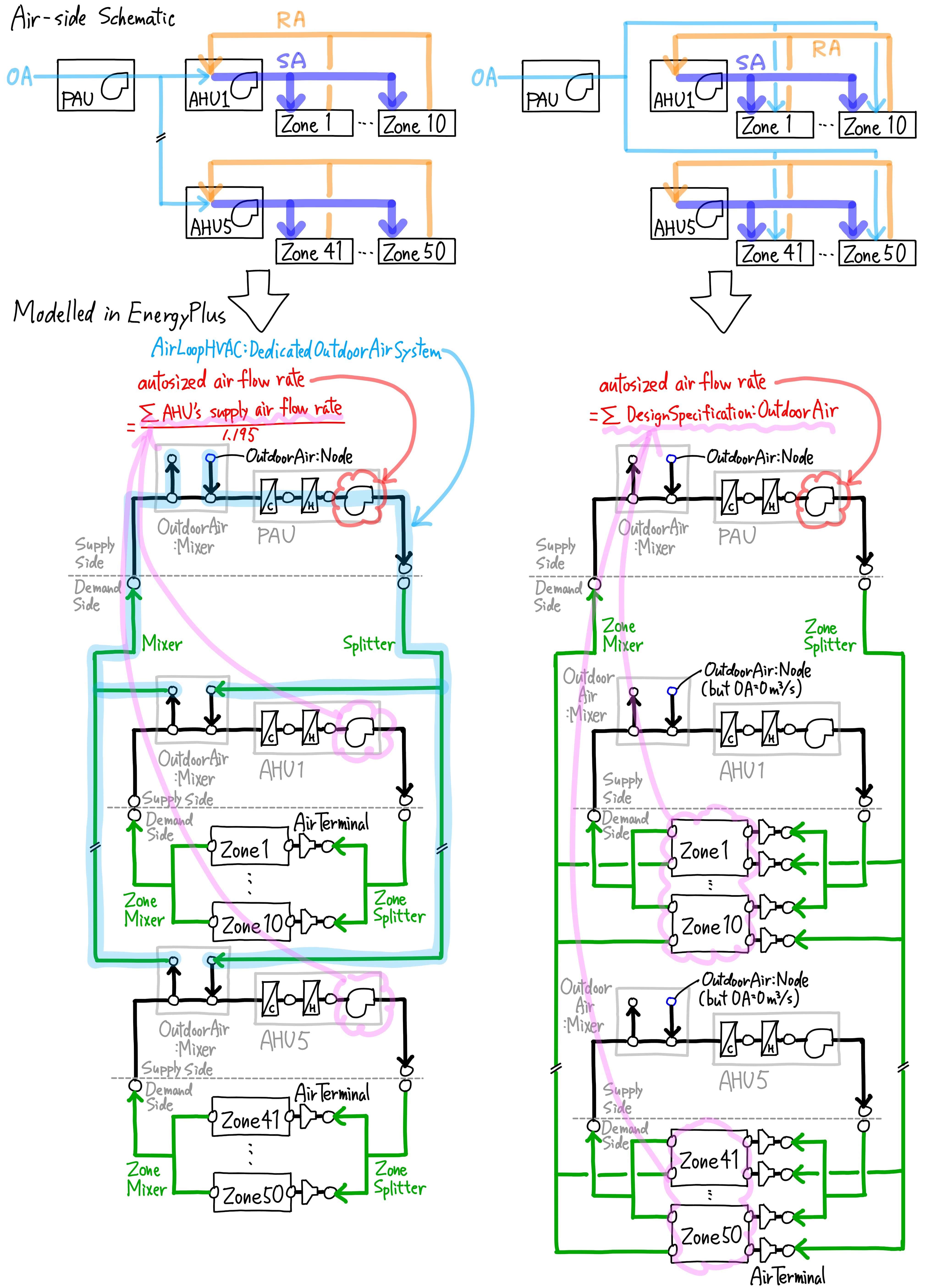
I have no idea why, but PAU's Fan:SystemModel design air flow rate is autosized by dividing the total supply air flow rate (not the total outoor air flow rate) of the connected AHUs by approximately 1.195. The following sizing summary table is an excerpt from the html file.
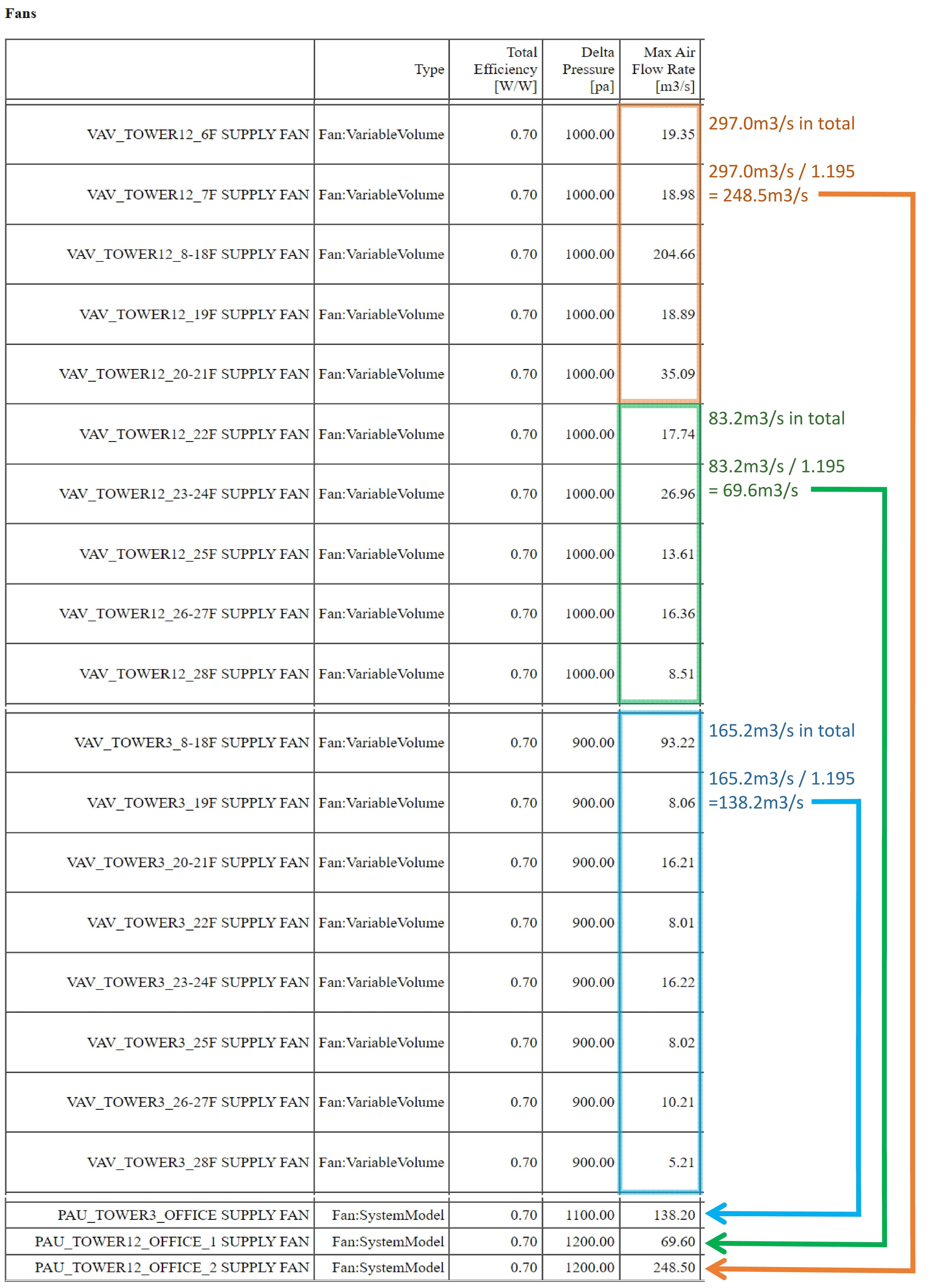
My expectation for AirLoopHVAC:DedicatedOutdoorAirSystem was that it would autosize the design PAU air flow rate by the sum of the required outdoor air flow rate for each zone defined by DesignSpecification:OutdoorAir, but in reality it was completely different. The above autosizing calculation is not appropriate at all.
I have another energy model that PAUs supply outdoor air not to AHUs but directly to each zone, so I know the original correct PAU air flow rate. PAU air flow rate with AirLoopHVAC:DedicatedOutdoorAirSystem was 7 to 10 times larger than the original correct PAU air flow rate.

| | 2 | No.2 Revision |
Let me add to @rraustad 's answer. His answer was a great clue. My conclusion is that AirLoopHVAC:DedicatedOutdoorAirSystem does not correctly autosize fan flow rate as well as coil capacity.
The flow rate fraction of Fan:SystemModel was always below Electric Power Minimum Flow Rate Fraction of 0.2, which resulted in the constant fan power. There are two possible causes for such a low flow fraction rate: Extremely low indoor CO2 concentration or Extremely high fan design air flow rate. My DCV setting is reasonable. 400ppm for outdoor CO2 concentration, 1000ppm for indoor threshould and 0.111person/m2 for office occupant density. Then, the cause is the latter.
I have no idea why, but PAU's Fan:SystemModel design air flow rate is autosized by dividing the total supply air flow rate (not the total outoor air flow rate) of the connected AHUs by approximately 1.195. The following sizing summary table is an excerpt from the html file.
My expectation for AirLoopHVAC:DedicatedOutdoorAirSystem was that it would autosize the design PAU air flow rate by the sum of the required outdoor air flow rate for each zone defined by DesignSpecification:OutdoorAir, but in reality it was completely different. The above autosizing calculation is not appropriate at all.
I have another energy model that PAUs supply outdoor air not to AHUs but directly to each zone, so I know the original correct PAU air flow rate. PAU air flow rate with AirLoopHVAC:DedicatedOutdoorAirSystem was 7 to 10 times larger than the original correct PAU air flow rate.
| | 3 | No.3 Revision |
Let me add to @rraustad 's answer. His answer was a great clue. My conclusion is that AirLoopHVAC:DedicatedOutdoorAirSystem does not correctly autosize fan flow rate as well as coil capacity.
The flow rate fraction of Fan:SystemModel was always below Electric Power Minimum Flow Rate Fraction of 0.2, which resulted in the constant fan power. There are two possible causes for such a low flow fraction rate: Extremely low indoor CO2 concentration or Extremely high fan design air flow rate. My DCV setting is reasonable. 400ppm for outdoor CO2 concentration, 1000ppm for indoor threshould and 0.111person/m2 for office occupant density. Then, the cause is the latter.
I have no idea why, but PAU's Fan:SystemModel design air flow rate is autosized by dividing the total supply air flow rate (not the total outoor air flow rate) of the connected AHUs by approximately 1.195. The following sizing summary table is an excerpt from the html file.
My expectation for AirLoopHVAC:DedicatedOutdoorAirSystem was that it would autosize the design PAU air flow rate by the sum of the required outdoor air flow rate for each zone defined by DesignSpecification:OutdoorAir, but in reality it was completely different. The above autosizing calculation is not appropriate at all.
I have another energy model that PAUs supply outdoor air not to AHUs but directly to each zone, so I know the original correct PAU air flow rate. PAU air flow rate with AirLoopHVAC:DedicatedOutdoorAirSystem was 7 to 10 times larger than the original correct PAU air flow rate.
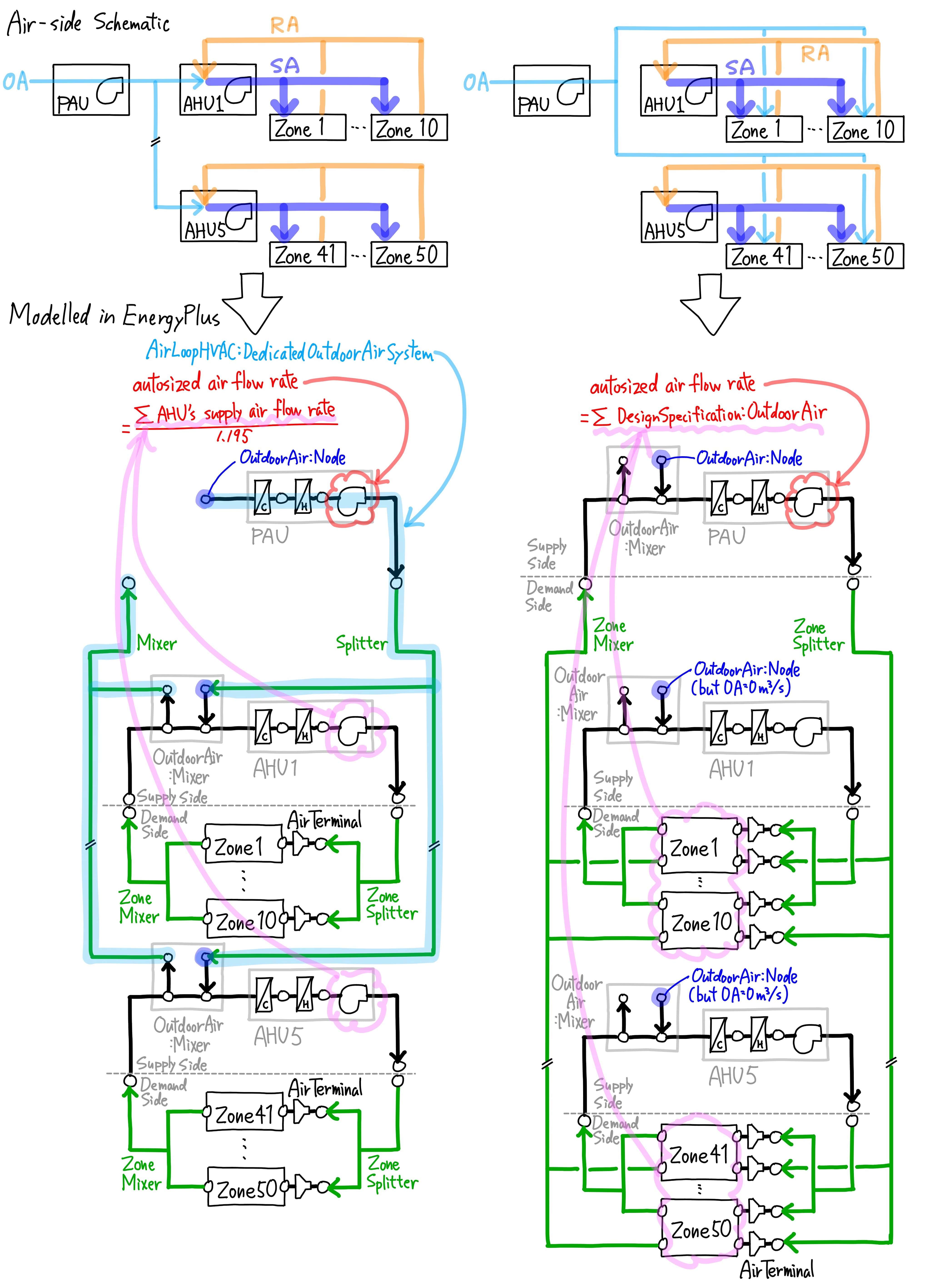
Just minor updates. I replaced my idf files and the above schematic. The simulation result has not changed.
I found that Inlet Node Name of AirLoopHVAC:Splitter did not match Air Outlet Node Name of Fan:SystemModel although there was no node connection error. Unlike AirloopHVAC, AirLoopHVAC:DedicatedOutdoorAirSystem has no concept of "Supply Side" and "Demand Side", so all Nodes are connected.

