Question-and-Answer Resource for the Building Energy Modeling Community
Get started with the Help page
Ask Your Question
3

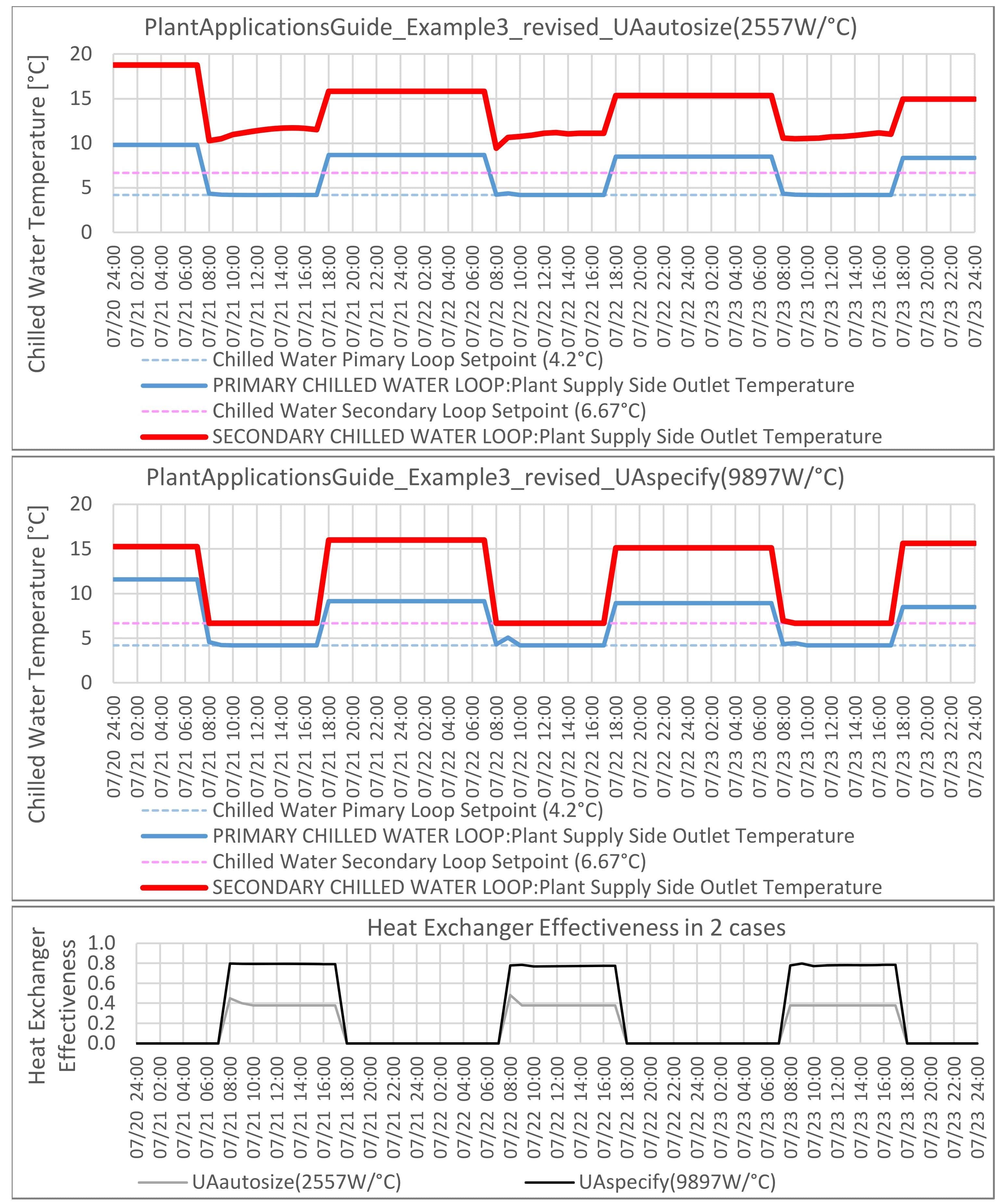
Secondary Chilled Water Loop Setpoint can't be controlled

asked 2021-05-15 15:27:07 -0500

Keigo's avatar

updated 2022-10-12 21:42:14 -0500

There is a similar post in the past, but that answer did not to work.

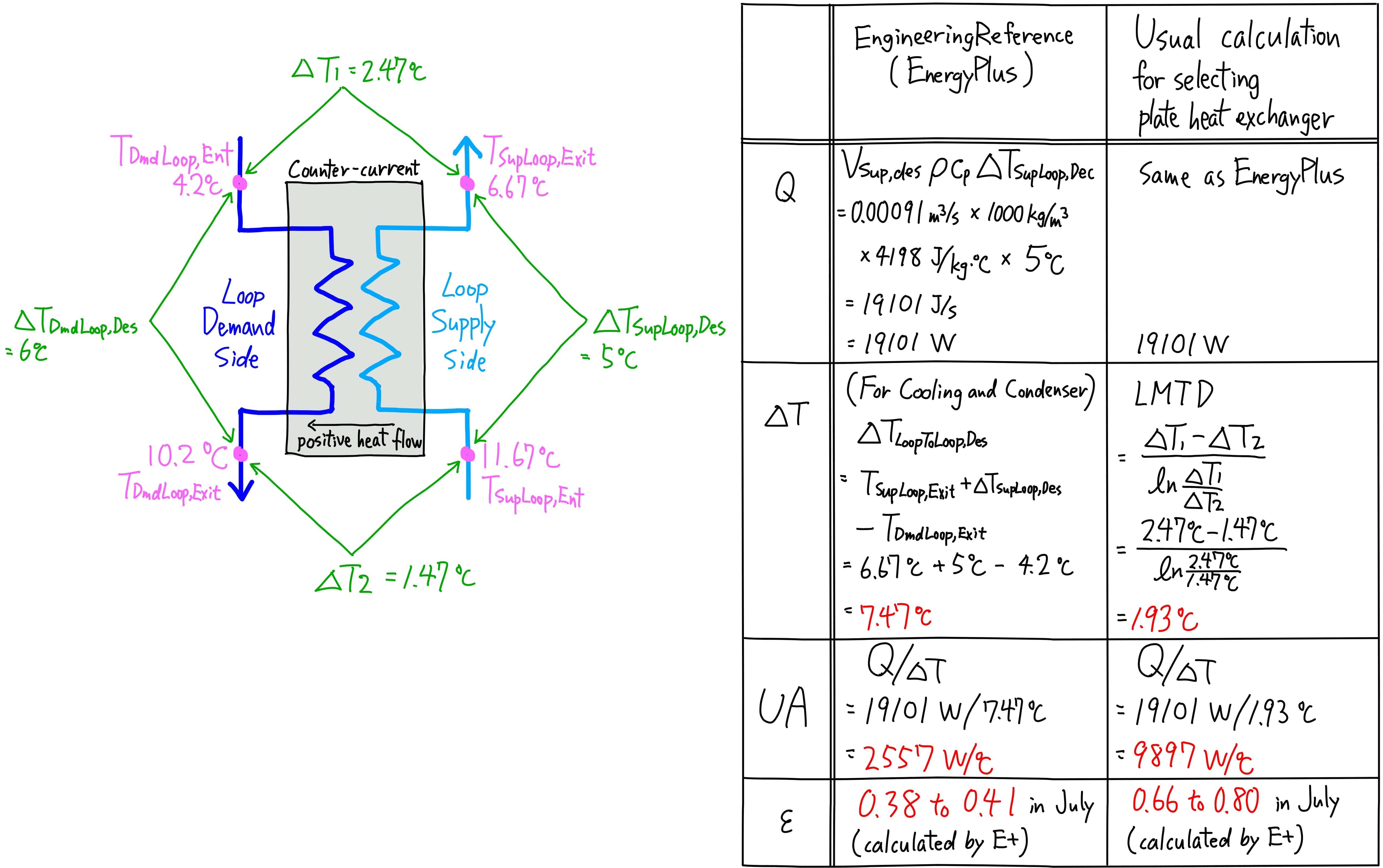
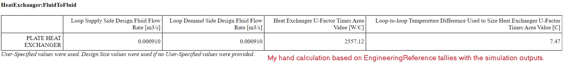
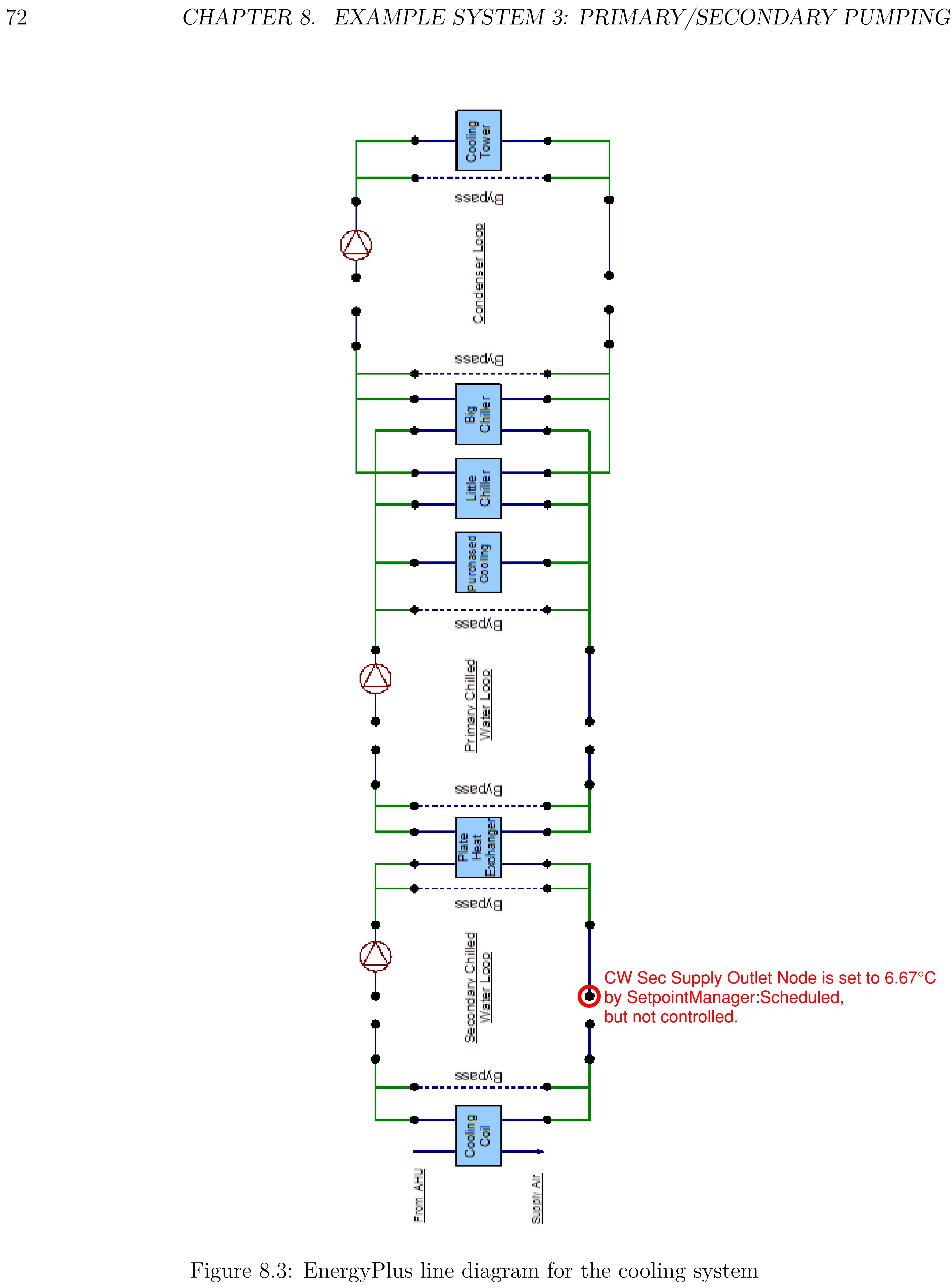
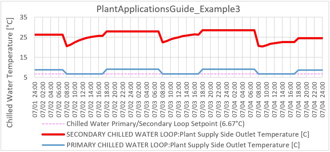
PlantApplicationsGuide_Example3.idf is one of ExampleFiles for EnergyPlus. It has Primary/Secondary Chilled Water Loop connencted through HeatExchanger:FluidToFluid.

CW Sec Supply Outlet Node is set to 6.67°C by SetpointManager:Scheduled, but actually it's not controlled and it's around 20 to 27°C,which is much higher than the setpoint of 6.67°C.

Does anyone know how to control this supply outlet temperature of secondary chilled water loop as desired?

image description

image description

Originally, Control Type of HeatExchanger:FluidToFluid is UncontrolledOn, so I changed it to CoolingSetpointModulated and input Heat Exchanger Setpoint Node Name, but in vain.

I tried the following changes, but none of them worked.

  • Increased Chiller Nominal Capacity and Pump Design Maximum Flow Rate.
  • Set EMS to override the Temperature Setpoint.
  • Changed theTemperature Setpoint higher than Temperature Setpoint of primary chilled water loop supply outlet.

Not only this example file, but also other my own model that uses HeatExchanger:FluidToFluid has similar Uncontrolled Temperature problem (but my model is a bit complicated, so I explained the problem with ExampleFile). Any insights would be appreciated.

edit retag flag offensive close merge delete

2 Answers

Sort by » oldest newest most voted
2

answered 2021-05-19 05:50:15 -0500

Keigo's avatar

updated 2021-05-19 08:47:01 -0500

Let me supplement the answer from @codybond.

Just changing Heat Exchange Model Type from CrossFlowBothUnmixed to Ideal (i.e., Heat Exchanger Effectiveness ε = 1) made the supply outlet temperature of secondary chilled water loop as desired (6.67°C). This is one of the solutions.

When we use Heat Exchange Model Type other than Ideal, the key parameter is Heat Exchanger U-Factor Times Area Value (UA). We need to set proper UA, but I found that autosize can't set the proper UA. How to calculate UA (the clipping of EngineerringReference below) is strange to me.

image description

I compared EngineeringReference with the way MEP engineers normally calculate the capacity of plate heat exchanger. IDF files are here. The version is 8.9.0. The UA in one file is autosized, in the other file it is manual input. They are both based on PlantApplicationsGuide_Example3.idf, but I changed Design Loop Exit Temperature and Loop Design Temperature Difference in Sizing:Plant to clarify which temperature is used forculculation and to make it a realistic model because the same setpoint of 6.67°C for both Primary Loop and Secondary Loop is physically impossible.

I think we usually use LMTD (Logarithmic Mean Temperature Difference) as delta T, but EngineeringReference uses a different equation for delta T (highlighted in the clipping above), which makes UA much smaller, and the Heat Exchanger Effectiveness decreases as well. When I manually input the UA that I calculated with LTMD (i.e., 9897W/°C), the supply outlet temperature of secondary chilled water loop became 6.67°C. This is what I wanted. Please see the charts below.

image description

image description

image description

edit flag offensive delete link more

Comments

Nice! Thanks for posting your work!

codybond's avatar codybond  ( 2021-05-19 09:18:43 -0500 )edit
1

answered 2021-05-17 09:40:30 -0500

Well, the good news is that it's trying to make a setpoint, but falling short. You're right to switch to CoolingSetpointModulated and assigning a Heat Exchanger Setpoint Node Name. I would try and autosize everything if you aren't already (especially all of the pumps), making sure your design parameters are set to values sufficient to make the desired setpoint (in particular Sizing:Plant).

Also try using an Ideal HX model type. Although even then you'll probably only be able to get to within 1 or 2C of the supply temp of 6.67C. Autosizing should give you some insight into the loads on the secondary loop though, as they may be such, compared to design values, that the loop just can't meet the operational demand.

edit flag offensive delete link more

Comments

@codybond thank you for your advise. I ran the case with everything autosized. In this ExamleFile, chiller capacity and pump flow rate didn't matter because the original setting was already optimised and has enough capacity. I think the key parameter is Heat Exchanger U-Factor Times Area Value, but it doesn't seem to be set properly by autosize. Even autosized, the supply outlet temperature of secondary loopI is still more than 5°C above the setpoint (6.67°C). Let me explain that in my Answer.

Ideal is super effective. Just changing to it made the temperature the setpoint.

Keigo's avatar Keigo  ( 2021-05-19 05:20:39 -0500 )edit

Your Answer

Please start posting anonymously - your entry will be published after you log in or create a new account.

Add Answer

Careers

Question Tools

1 follower

Stats

Asked: 2021-05-15 15:27:07 -0500

Seen: 295 times

Last updated: May 19 '21