Question-and-Answer Resource for the Building Energy Modeling Community
| | 1 | initial version |
Let me supplement the answer from @codybond.
Just changing Heat Exchange Model Type from CrossFlowBothUnmixed to Ideal (i.e., Heat Exchanger Effectiveness ε = 1) made the supply outlet temperature of secondary chilled water loop as desired (6.67°C). This is one of the solutions.
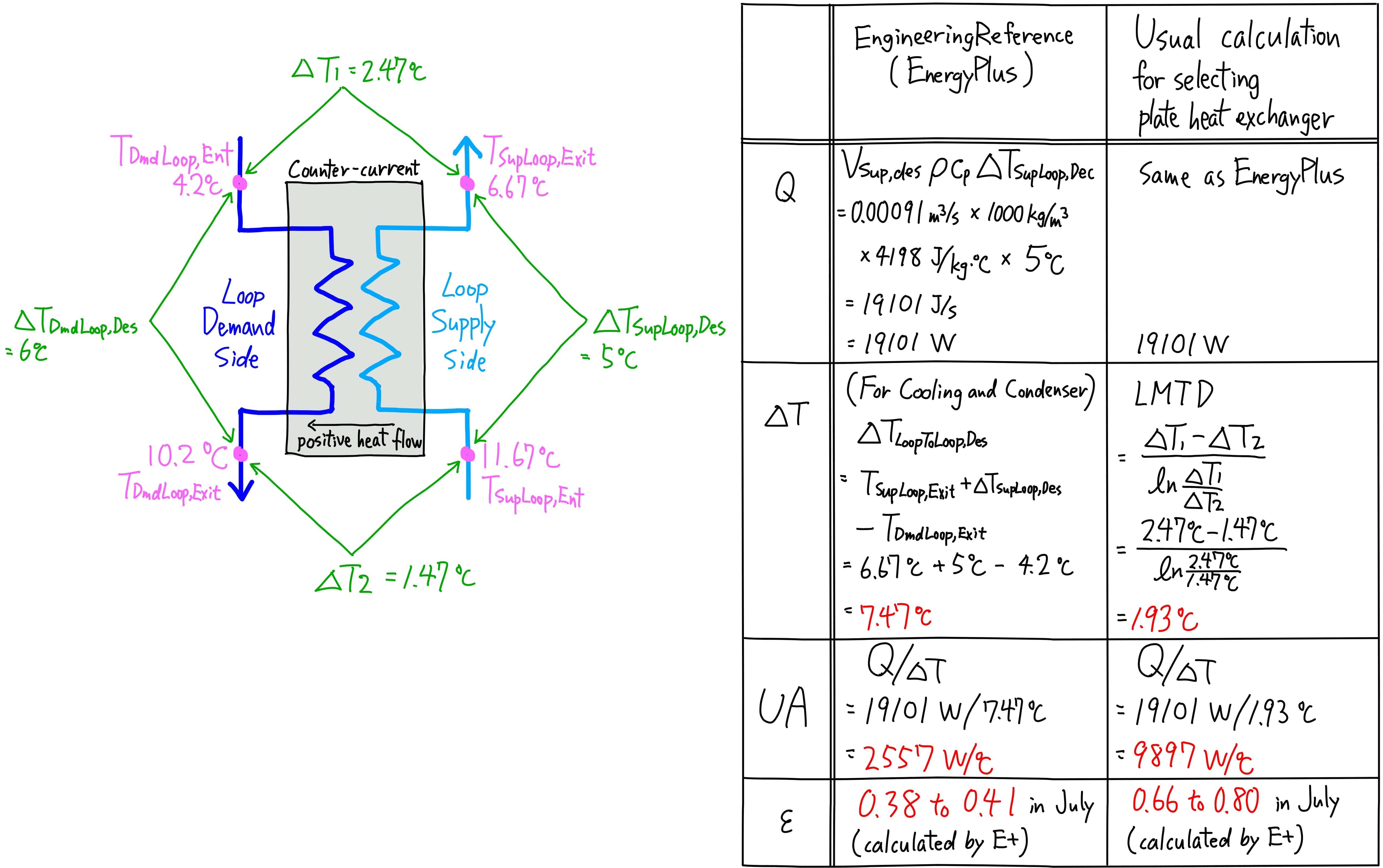
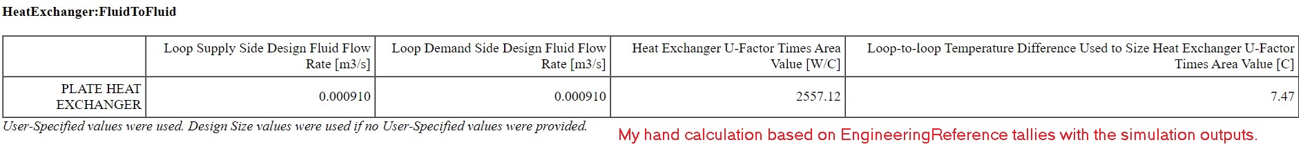
When we use Heat Exchange Model Type other than Ideal, the key parameter is Heat Exchanger U-Factor Times Area Value (UA). We need to set proper UA, but I found that autosize can't set the proper UA. How to calculate UA (the clipping of EngineerringReference below) is strange to me.

I compared EngineeringReference with the way MEP engineers normally calculate the capacity of plate heat exchanger. IDF files are here. The version is 8.9.0. The UA in one file is autosized, in the other file it is manual input. They are both based on PlantApplicationsGuide_Example3.idf, but I changed Design Loop Exit Temperature and Loop Design Temperature Difference in Sizing:Plant to clarify which temperature is used forculculation and to make it a realistic model because the same setpoint of 6.67°C for both Primary Loop and Secondary Loop is physically impossible.
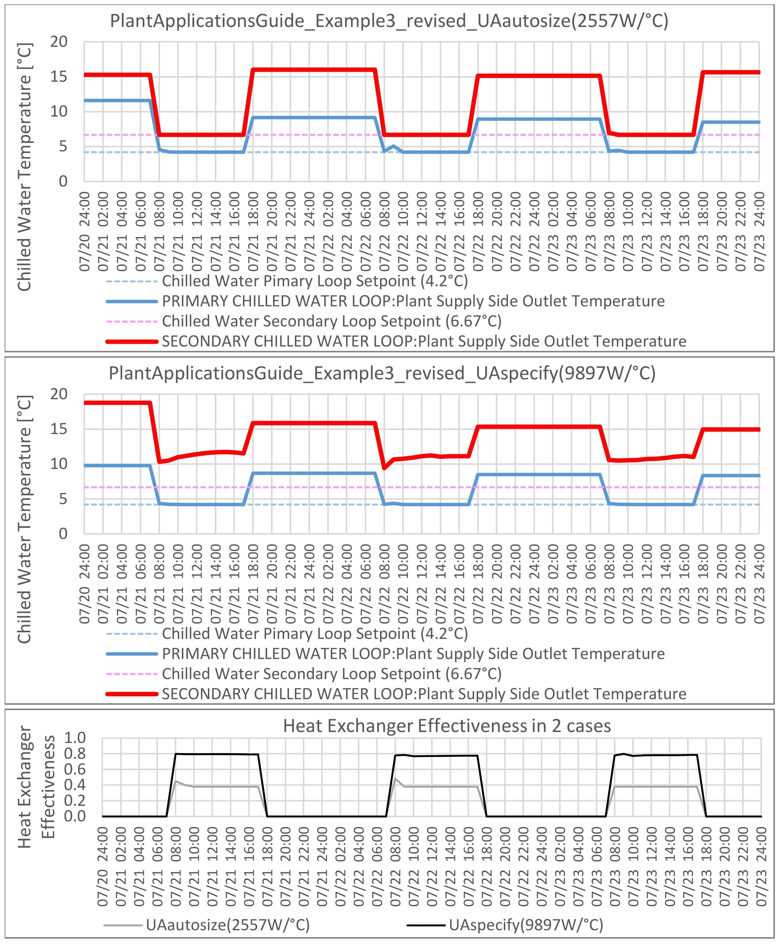
I think we normally use LTMD (Logarithmic Mean Temperature Difference) as delta T, but EngineeringReference uses a different equation for delta T (highlighted in the clipping above), which makes UA much smaller, and the Heat Exchanger Effectiveness decreases as well. When I manually input the UA that I calculated with LTMD (i.e., 9897W/°C), the supply outlet temperature of secondary chilled water loop became 6.67°C. This is what I wanted. Please see the charts below.

| | 2 | No.2 Revision |
Let me supplement the answer from @codybond.
Just changing Heat Exchange Model Type from CrossFlowBothUnmixed to Ideal (i.e., Heat Exchanger Effectiveness ε = 1) made the supply outlet temperature of secondary chilled water loop as desired (6.67°C). This is one of the solutions.
When we use Heat Exchange Model Type other than Ideal, the key parameter is Heat Exchanger U-Factor Times Area Value (UA). We need to set proper UA, but I found that autosize can't set the proper UA. How to calculate UA (the clipping of EngineerringReference below) is strange to me.
I compared EngineeringReference with the way MEP engineers normally calculate the capacity of plate heat exchanger. IDF files are here. The version is 8.9.0. The UA in one file is autosized, in the other file it is manual input. They are both based on PlantApplicationsGuide_Example3.idf, but I changed Design Loop Exit Temperature and Loop Design Temperature Difference in Sizing:Plant to clarify which temperature is used forculculation and to make it a realistic model because the same setpoint of 6.67°C for both Primary Loop and Secondary Loop is physically impossible.
I think we normally use LTMD (Logarithmic Mean Temperature Difference) as delta T, but EngineeringReference uses a different equation for delta T (highlighted in the clipping above), which makes UA much smaller, and the Heat Exchanger Effectiveness decreases as well. When I manually input the UA that I calculated with LTMD (i.e., 9897W/°C), the supply outlet temperature of secondary chilled water loop became 6.67°C. This is what I wanted. Please see the charts below.

| | 3 | No.3 Revision |
Let me supplement the answer from @codybond.
Just changing Heat Exchange Model Type from CrossFlowBothUnmixed to Ideal (i.e., Heat Exchanger Effectiveness ε = 1) made the supply outlet temperature of secondary chilled water loop as desired (6.67°C). This is one of the solutions.
When we use Heat Exchange Model Type other than Ideal, the key parameter is Heat Exchanger U-Factor Times Area Value (UA). We need to set proper UA, but I found that autosize can't set the proper UA. How to calculate UA (the clipping of EngineerringReference below) is strange to me.
I compared EngineeringReference with the way MEP engineers normally calculate the capacity of plate heat exchanger. IDF files are here. The version is 8.9.0. The UA in one file is autosized, in the other file it is manual input. They are both based on PlantApplicationsGuide_Example3.idf, but I changed Design Loop Exit Temperature and Loop Design Temperature Difference in Sizing:Plant to clarify which temperature is used forculculation and to make it a realistic model because the same setpoint of 6.67°C for both Primary Loop and Secondary Loop is physically impossible.
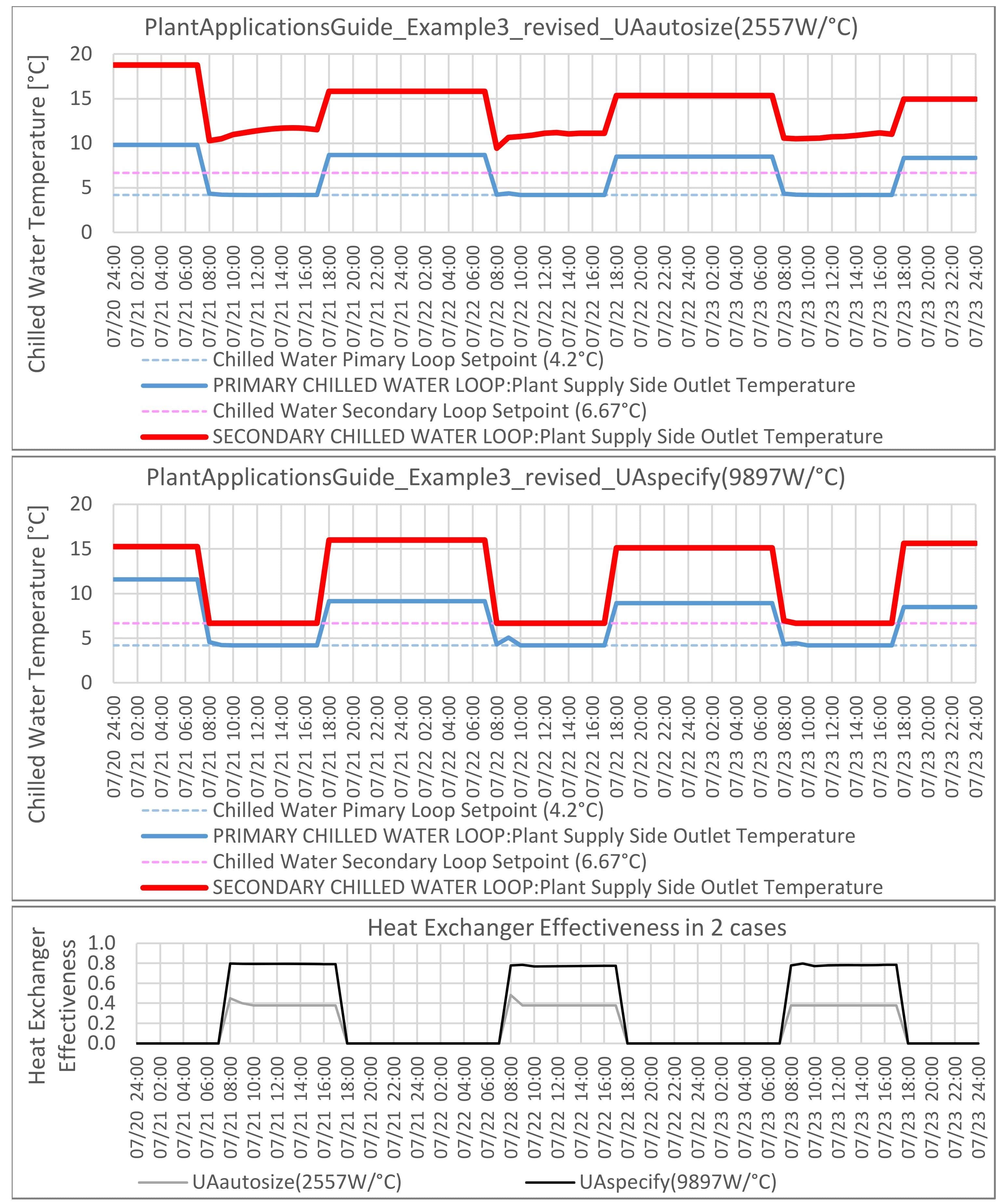
I think we normally use LTMD (Logarithmic Mean Temperature Difference) as delta T, but EngineeringReference uses a different equation for delta T (highlighted in the clipping above), which makes UA much smaller, and the Heat Exchanger Effectiveness decreases as well. When I manually input the UA that I calculated with LTMD (i.e., 9897W/°C), the supply outlet temperature of secondary chilled water loop became 6.67°C. This is what I wanted. Please see the charts below.
| | 4 | No.4 Revision |
Let me supplement the answer from @codybond.
Just changing Heat Exchange Model Type from CrossFlowBothUnmixed to Ideal (i.e., Heat Exchanger Effectiveness ε = 1) made the supply outlet temperature of secondary chilled water loop as desired (6.67°C). This is one of the solutions.
When we use Heat Exchange Model Type other than Ideal, the key parameter is Heat Exchanger U-Factor Times Area Value (UA). We need to set proper UA, but I found that autosize can't set the proper UA. How to calculate UA (the clipping of EngineerringReference below) is strange to me.
I compared EngineeringReference with the way MEP engineers normally calculate the capacity of plate heat exchanger. IDF files are here. The version is 8.9.0. The UA in one file is autosized, in the other file it is manual input. They are both based on PlantApplicationsGuide_Example3.idf, but I changed Design Loop Exit Temperature and Loop Design Temperature Difference in Sizing:Plant to clarify which temperature is used forculculation and to make it a realistic model because the same setpoint of 6.67°C for both Primary Loop and Secondary Loop is physically impossible.
I think we normally usually use LTMDLMTD (Logarithmic Mean Temperature Difference) as delta T, but EngineeringReference uses a different equation for delta T (highlighted in the clipping above), which makes UA much smaller, and the Heat Exchanger Effectiveness decreases as well. When I manually input the UA that I calculated with LTMD (i.e., 9897W/°C), the supply outlet temperature of secondary chilled water loop became 6.67°C. This is what I wanted. Please see the charts below.