Question-and-Answer Resource for the Building Energy Modeling Community
| | 1 | initial version |
Without looking at the EnergyPlus IDF, I would first confirm that this happens when there is chilled water flow by adding a "System Node Mass Flow Rate" output variable for the supply-side outlet node to these charts. If these temperature differences occur when there is no chilled water flow, then you don't have an issue.
If these temperature differences occur when there is chilled water flow, then next I would confirm that this is also looking at the final node leaving the supply-side of the loop and not the outlet node directly after each HXF component. This HXF outlet water can mix with the water flowing through the parallel bypass pipes, causing increased temperatures on the demand side.
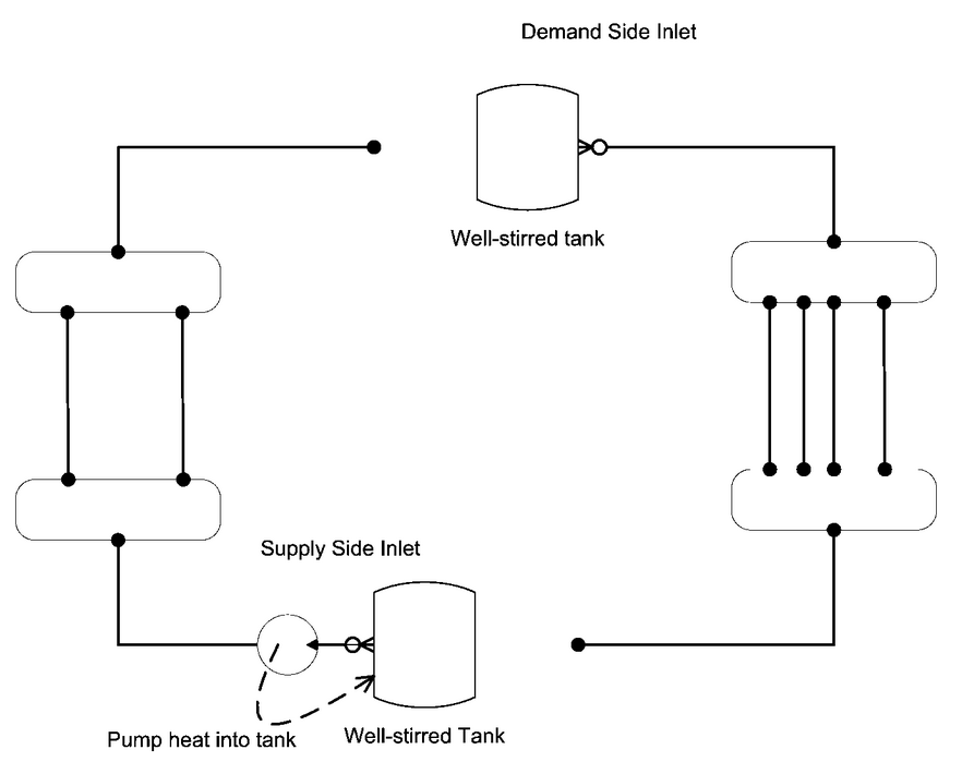
If both of those things are confirmed, then this is behavior is likely due to low loop volume, low loop flow rates, or low loop fluid heat capacity that affects the way that EnergyPlus accounts for liquid heat storage capacity and pump friction. For the supply and demand sides of water plant loops, EnergyPlus uses an "imaginary" storage tank at the first inlet node that changes the water temperature there. If you were to compare temperatures of supply-side outlet node to demand-side inlet node, even though they are immediately in series, they will be different values because of this (unless you set the loop heat capacitance to zero). See screenshot below from the Engineering Reference section I linked to above.
To confirm that this is the case, you can add "Plant Supply Side Lumped Capacitance Heat Storage Rate" and similar output variables to investigate if this is causing the temperature differences you see.
| | 2 | No.2 Revision |
Without looking at the EnergyPlus IDF, I would first confirm that this happens when there is chilled water flow by adding a "System Node Mass Flow Rate" output variable for the supply-side outlet node to these charts. If these temperature differences occur when there is no chilled water flow, then you don't have an issue.
If these temperature differences occur when there is chilled water flow, then next I would confirm that this is also looking at the final node leaving the supply-side of the loop and not the outlet node directly after each HXF component. This HXF outlet water can mix with the water flowing through the parallel bypass pipes, causing increased temperatures on the demand side.
If both of those things are confirmed, then this is behavior is likely due to low loop volume, low loop flow rates, or low loop fluid heat capacity that affects the way that EnergyPlus accounts for liquid heat storage capacity and pump friction. For the supply and demand sides of water plant loops, EnergyPlus uses an "imaginary" storage tank at the first inlet node that changes the water temperature there. If you were to compare temperatures of supply-side outlet node to demand-side inlet node, even though they are immediately in series, they will be different values because of this (unless you set the loop heat capacitance to zero). See screenshot below from the Engineering Reference section I linked to above.
To confirm that this is the case, you can add "Plant Supply Side Lumped Capacitance Heat Storage Rate" and similar output variables to investigate if this is causing the temperature differences you see.
UPDATE
Thanks for adding demand inlet node temperatures and flow rates to the chart, that helps. If the temperature for supply side outlet node and demand side inlet node are equal, then it's not the imaginary storage tank and also likely not the plant loop iterations. One other possible explanation is that you have pipes with sleeve losses instead of adiabatic pipes. This would explain warming of chilled water after supply outlet node and before reaching the fan coil. It's hard for us to know the proper solution without seeing your IDF, if you can link to the IDF it would be great.


