Question-and-Answer Resource for the Building Energy Modeling Community
Get started with the Help page
Ask Your Question
3

Example AirFlowNetwork Drawing for IDF

asked 2020-02-07 17:27:36 -0600

mldichter's avatar

updated 2020-02-12 13:38:32 -0600

Is there a drawing anywhere corresponding to an IDF of how all the stuff in the AirFlowNetwork objects are linked together and where the nodes are? I have a working AirLoop that I'm trying to add AirFlowNetwork objects for modeling thermal losses and leaks from ducts in the attic. I've been trying to use the AirflowNetwork_Attic_Duct.idf example file as a template, but I have not gotten anything to work. I looked in the IO Ref and the comments in the top of a couple energyplus example files, but I haven't found anything.

EDIT
In the AirflowNetwork_Attic_Duct.idf example file in particular, there is a single node in the AirLoop that is referenced by two different AFN nodes, which are then referenced by AirflowNetwork:Distribution:Linkage objects.

AirflowNetwork:Distribution:Node,
    MainInletNode,           !- Name
    Air Loop Inlet Node,     !- Component Name or Node Name
    Other,                   !- Component Object Type or Node Type
    1;                       !- Node Height {m}

AirflowNetwork:Distribution:Node,
    FanInletNode,            !- Name
    Air Loop Inlet Node,     !- Component Name or Node Name
    Other,                   !- Component Object Type or Node Type
    1;                       !- Node Height {m}

AirflowNetwork:Distribution:Linkage,
    SystemReturnLink,        !- Name
    MainReturnNode,          !- Node 1 Name
    MainInletNode,           !- Node 2 Name
    AirLoopReturn;           !- Component Name

AirflowNetwork:Distribution:Linkage,
    SystemInletLink,         !- Name
    MainInletNode,           !- Node 1 Name
    FanInletNode,            !- Node 2 Name
    MainReturn,              !- Component Name
    Occupied Thermal Zone;   !- Thermal Zone Name

AirflowNetwork:Distribution:Linkage,
    SupplyFanLink,           !- Name
    FanInletNode,            !- Node 1 Name
    FanOutletNode,           !- Node 2 Name
    Supply Fan 1;            !- Component Name

There are other nodes and connections in the AirflowNetwork_Attic_Duct.idf example file that I'm not really sure what they mean. That's why having a drawing of how things are connected in the AirflowNetwork_Attic_Duct.idf would be really useful for learning how to use the AirFlowNetwork. Something like a diagram with the node names labeled in the AirLoop and AirFlowNetwork, hand drawn, and scanned would be really useful.

POST SCRIPT
There seems to be some confusion about creation of a diagram to learn how to make an AirFlowNetwork in EnergyPlus. I don't need to be able to visualize EVERY AirFlowNetwork connections in any arbitrary IDF file, I just need ONE example diagram for ONE IDF file. For example, here is a nice diagram of an airloop from the IO Ref. There is no such example diagram for making ducts in the AirFlowNetwork in the IO Ref. image description
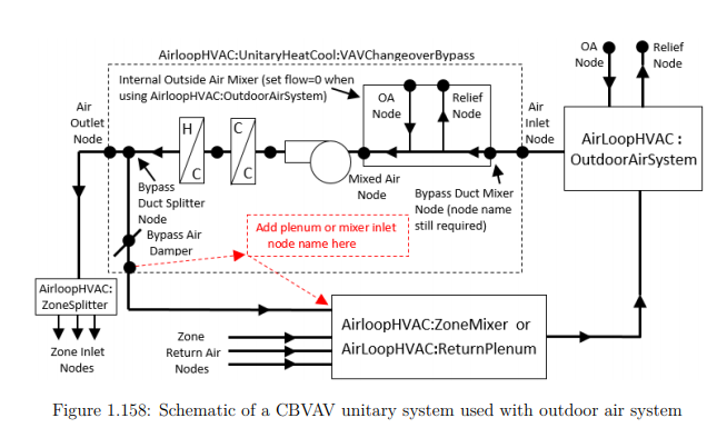
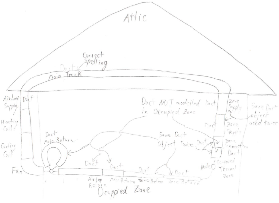
I will now attempt to make my own drawing for the AirFlowNetwork in the AirflowNetwork_Attic_Duct.idf example file using a piece of paper, a pencil, and potentially, an eraser. WARNING: TO ANYONE WHO WANTS A CORRECT VISUALIZATION of the AirFlowNetwork from the AirflowNetwork_Attic_Duct.idf example file, THIS DRAWING IS PROBABLY WRONG SINCE I DON'T KNOW HOW TO CORRECTLY MAKE AN AirFlowNetwork in EnergyPlus.
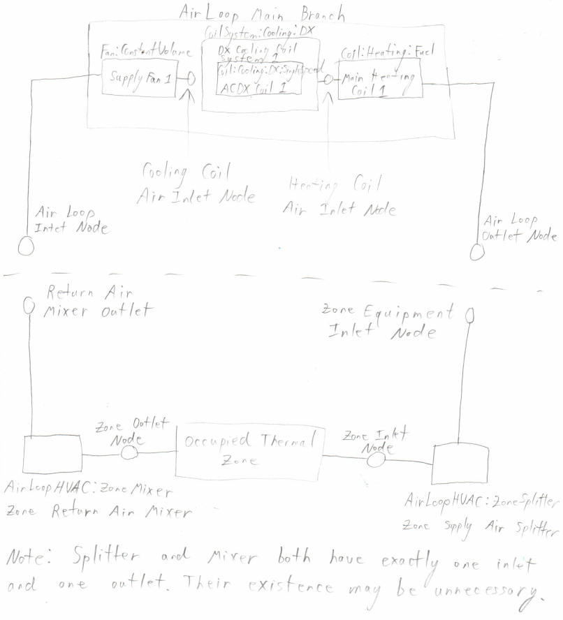
Here is a picture of the AirLoop with equipment and node names for reference in the AirFlowNetwork digram. image description
Here is a diagram of the AirFlowNetwork. image description
edit retag flag offensive close merge delete

Comments

I have added an issue for EnergyPlus. https://github.com/NREL/EnergyPlus/is...

mldichter's avatar mldichter  ( 2020-02-10 16:02:29 -0600 )edit
1

The original issue I posted has been closed. The new issue is https://github.com/NREL/EnergyPlus/is... posted by @Jason DeGraw.

mldichter's avatar mldichter  ( 2020-02-11 15:21:53 -0600 )edit

2 Answers

Sort by ยป oldest newest most voted
2

answered 2020-02-09 16:42:38 -0600

Since the addition of the JSON version of the input file, it's gotten a lot easier to do processing of the input outside of EnergyPlus proper, so that's what I did with an AirflowNetwork model "audit" script that got added last year:

https://github.com/NREL/EnergyPlus/bl...

It will check a model in epJSON format for a number of potential problems and generate a graph that can be visualized. Unfortunately it doesn't yet do any checks of distribution models and wouldn't catch the issue you've pointed out (those are hard to catch because the system of equations still works). It is mainly looking at linkage counts because I've been using it to examine larger models that have many linkages. Distribution support will be added at some point, but a feature request would definitely help that get done sooner.

On your original question, it's going to roughly follow the loop layout, I've done several of these myself but not for this particular model (and I fear those are all lost now). Once the visualization script does support distribution, I suppose we could include those visualizations someplace, but as with the script, having that feedback as a feature request (e.g. "add AFN network diagrams for the example files" or something) will help get it done.

edit flag offensive delete link more

Comments

1

@Jason DeGraw Thank you for the information about the uncaught node issue. I'll try and modify the example IDF and see if I can remove the duplicate node reference in the AirFlowNetwork.

mldichter's avatar mldichter  ( 2020-02-10 13:11:46 -0600 )edit
1

@Jason DeGraw I'm attempting to draw out the relationship between the AirLoop and the AirFlowNetwork and I'm finding even more weird stuff. I've invested quite a bit of time in the AirflowNetwork_Attic_Duct.idf so I'll finish, but this isn't a great file for illustrative purposes. What would you say is the most correct EnergyPlus example file? Or do you know who would know that?

mldichter's avatar mldichter  ( 2020-02-10 15:21:24 -0600 )edit

@mldichter The duplication of nodes isn't great, but that doesn't mean the network isn't legit. Basically if the solver works, the network is legit (it won't work otherwise). In this case it may actually even match the modeling intent (yes, perhaps by accident). Most of the AFN "airflow element" objects (like ducts, cracks, etc.) are reusable, so reuse is acceptable. Have you run some of the non-distribution cases and understood how those are built? Distribution modeling is much more difficult, so I usually recommend starting there and building up from there.

Jason DeGraw's avatar Jason DeGraw  ( 2020-02-10 20:01:02 -0600 )edit
1

@Jason DeGraw I did actually, but at the same time I won't be using the full power of the AFN objects. The goal of the project is to model leaks and thermal losses from ducts in the attic, so my IDF and AFN objects shouldn't be too complicated. I'm hoping I don't have to spend too much time on airflow within the occupied space and attic since air distribution in the occupied space isn't important to the project and the attic isn't sealed, respectively.

mldichter's avatar mldichter  ( 2020-02-11 10:36:43 -0600 )edit
1

answered 2020-02-09 07:52:04 -0600

If what you're looking for is a diagram of Airflow Newtork (AFN) object connections defined in the IDF, similar to the SVG output file that diagrams HVAC connections in the IDF, then you're out of luck. I imagine that this would be a large undertaking, since there is a combination of AFN objects that are abstract and define controls and other non-physical parameters, which don't really have a great place to be shown in diagrams, as well as AFN objects that do represent a physical aspect of the model (ducting, holes in surface, etc.). Those physical aspects should really be overlaid on the model's geometry in order to help illustrate what they are doing, which is the real crux of the problem.

Perhaps someday an EnergyPlus interface will provide this capability, but in the meantime, if you feel that this should be a new feature of EnergyPlus you should create a feature request on the EnergyPlus Github and ask others to vote for that with a "thumbs up" to let the development team know that users would find it useful.

Perhaps your best resource to understand how AFN objects are linked together in general is the figure in the IO Ref that shows Relationships among AFN objects.

Usually, if the IO Ref doesn't contain diagrams to explain various input fields, then the next best place to look is the Engineering Reference. However, for the Airflow Network (AFN) model, the Engineering Reference contains diagrams about different potential flow processes that it can accommodate and not how the specific AFN objects defined in the IDF are are used in the flow process calucalations. Searching for "airflow network" in the other documentation files that come with EnergyPlus turns up a section of the .eio output file that contains some descriptions of AFN controls and wind direction/pressure coefficients, but again no diagrams.

edit flag offensive delete link more

Comments

1

@Aaron Boranian I just updated the post. I'm not looking for a way to visualize the AFN in any IDF, just a hand drawn diagram with components and nodes labeled for the AirflowNetwork_Attic_Duct.idf example file would be useful. A hand drawn diagram shouldn't take too long to make, and then it's a simple scan and upload as an answer.

mldichter's avatar mldichter  ( 2020-02-09 09:57:57 -0600 )edit
1

@Aaron Boranian I'm attempting to draw out the relationship between the AirLoop and the AirFlowNetwork and I'm finding even more weird stuff. I've invested quite a bit of time in the AirflowNetwork_Attic_Duct.idf so I'll finish, but this isn't a great file for illustrative purposes. What would you say is the most correct EnergyPlus example file? Or do you know who would know that?

mldichter's avatar mldichter  ( 2020-02-10 15:21:58 -0600 )edit

Your Answer

Please start posting anonymously - your entry will be published after you log in or create a new account.

Add Answer

Training Workshops

Careers

Question Tools

3 followers

Stats

Asked: 2020-02-07 17:27:36 -0600

Seen: 439 times

Last updated: Feb 12 '20