Is there a drawing anywhere corresponding to an IDF of how all the stuff in the AirFlowNetwork objects are linked together and where the nodes are? I have a working AirLoop that I'm trying to add AirFlowNetwork objects for modeling thermal losses and leaks from ducts in the attic. I've been trying to use the AirflowNetwork_Attic_Duct.idf example file as a template, but I have not gotten anything to work. I looked in the IO Ref and the comments in the top of a couple energyplus example files, but I haven't found anything.
EDIT
In the AirflowNetwork_Attic_Duct.idf example file in particular, there is a single node in the AirLoop that is referenced by two different AFN nodes, which are then referenced by AirflowNetwork:Distribution:Linkage objects.
AirflowNetwork:Distribution:Node,
    MainInletNode,           !- Name
    Air Loop Inlet Node,     !- Component Name or Node Name
    Other,                   !- Component Object Type or Node Type
    1;                       !- Node Height {m}

AirflowNetwork:Distribution:Node,
    FanInletNode,            !- Name
    Air Loop Inlet Node,     !- Component Name or Node Name
    Other,                   !- Component Object Type or Node Type
    1;                       !- Node Height {m}

AirflowNetwork:Distribution:Linkage,
    SystemReturnLink,        !- Name
    MainReturnNode,          !- Node 1 Name
    MainInletNode,           !- Node 2 Name
    AirLoopReturn;           !- Component Name

AirflowNetwork:Distribution:Linkage,
    SystemInletLink,         !- Name
    MainInletNode,           !- Node 1 Name
    FanInletNode,            !- Node 2 Name
    MainReturn,              !- Component Name
    Occupied Thermal Zone;   !- Thermal Zone Name

AirflowNetwork:Distribution:Linkage,
    SupplyFanLink,           !- Name
    FanInletNode,            !- Node 1 Name
    FanOutletNode,           !- Node 2 Name
    Supply Fan 1;            !- Component Name
There are other nodes and connections in the AirflowNetwork_Attic_Duct.idf example file that I'm not really sure what they mean. That's why having a drawing of how things are connected in the AirflowNetwork_Attic_Duct.idf would be really useful for learning how to use the AirFlowNetwork. Something like a diagram with the node names labeled in the AirLoop and AirFlowNetwork, hand drawn, and scanned would be really useful.
POST SCRIPT
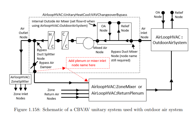
There seems to be some confusion about creation of a diagram to learn how to make an AirFlowNetwork in EnergyPlus. I don't need to be able to visualize EVERY AirFlowNetwork connections in any arbitrary IDF file, I just need ONE example diagram for ONE IDF file. For example, here is a nice diagram of an airloop from the IO Ref. There is no such example diagram for making ducts in the AirFlowNetwork in the IO Ref.
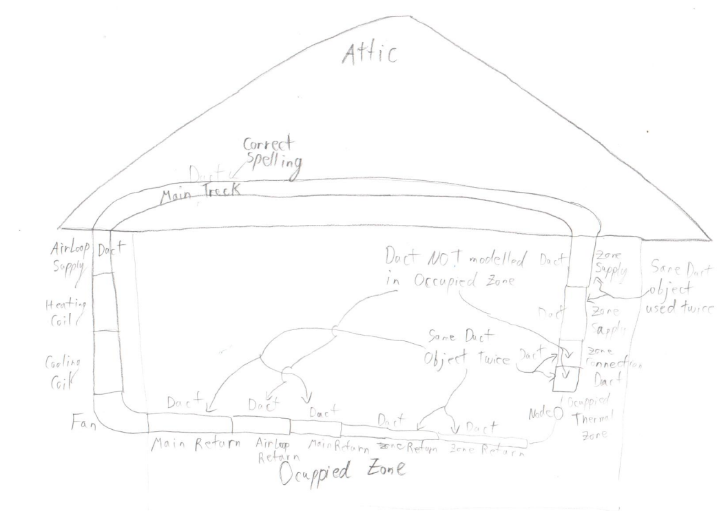
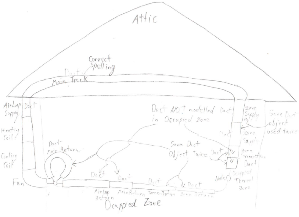
I will now attempt to make my own drawing for the AirFlowNetwork in the AirflowNetwork_Attic_Duct.idf example file using a piece of paper, a pencil, and potentially, an eraser. WARNING: TO ANYONE WHO WANTS A CORRECT VISUALIZATION of the AirFlowNetwork from the AirflowNetwork_Attic_Duct.idf example file, THIS DRAWING IS PROBABLY WRONG SINCE I DON'T KNOW HOW TO CORRECTLY MAKE AN AirFlowNetwork in EnergyPlus.
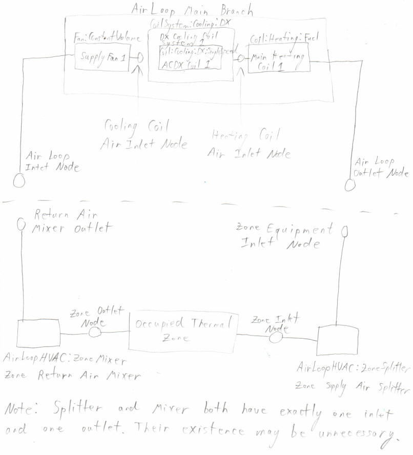
Here is a picture of the AirLoop with equipment and node names for reference in the AirFlowNetwork digram.
Here is a diagram of the AirFlowNetwork. TO BE ADDEDAirFlowNetwork.