Question-and-Answer Resource for the Building Energy Modeling Community
Get started with the Help page
Ask Your Question
1

Overlapping surfaces in Radiance

asked 2018-11-14 07:07:08 -0600

john.everist's avatar

updated 2018-11-14 07:43:09 -0600

Hello Community

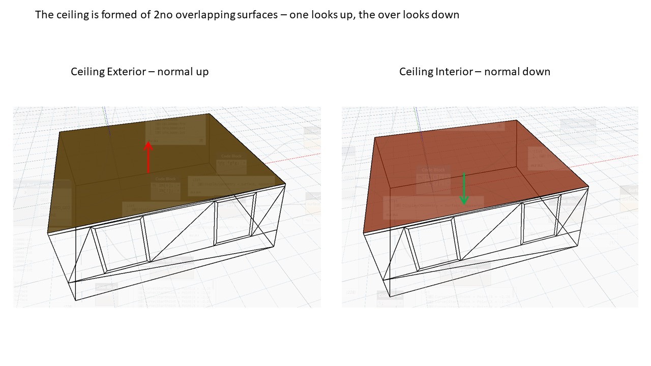
I'm reviewing IES VE daylight calculations using the radiance (radiance 5.1) module. On inspecting a model of a room I see that all room objects(wall, floor, ceiling) are made from 2 identical surfaces with flipped normals. For example, the 'ceiling' has 2no identical polygons - 1 looks up and the over looks down. See below.

image description

My understanding is that this will at best extend calculation time or at worse cause incorrect result (duplicate rays from each surface or use the exterior reflectance when the interior was required.

Does anyone know the definite answer? Are this results valid? What is the effect of duplicate surfaces overlapping?

Thankyou.

edit retag flag offensive close merge delete

3 Answers

Sort by » oldest newest most voted
3

answered 2018-11-16 10:34:50 -0600

updated 2018-11-16 10:38:54 -0600

If the two surfaces are actually coincident, not just close to each other, then which surface is "hit" will be (somewhat) random. It won't matter with backface visibility "off", which is the default, for most material types. There are only a few materials that do not adjust their orientation to face the incoming ray. These special one-sided material types are light, illum, dielectric, interface, BRTDfunc, and BSDF if I remember right. (The new "aBSDF" material also, but this isn't included in 5.1.)

I don't recommend turning off backface visibility if your surfaces are truly coincident, as this would cause rays to randomly pass through both surfaces in some places. If they are separated by some distance, however small, and face away from each other, then turning backface visibility off should make no difference to the results. The only real value of turning off backface visibility that I've found is when you are trying to make sure of your surface orientation for the materials I listed above that care, or when you are trying to see "into" a room from the outside, where you have deliberately oriented all your wall surfaces to the interior.

Just to be clear, having coincident surfaces with different materials is a definite error, which will result in those surfaces being randomly painted with one material or the other, and changing the backface visibility flag will only cause holes to appear from either side. You need these surfaces to have a small gap between them, with the surface material you want on the appropriate side of the model. There is no workaround for such a modeling problem.
edit flag offensive delete link more
1

answered 2018-11-14 11:13:22 -0600

You will need to check whether the backface visibility ("-bv") flag is given to Radiance. If it is, then rays only encounter the surface with normal facing the ray's origin. This is a useful way to give the sides of a surface different reflectance values.

If the -bv flag is not given, the ray might hit either surface and potentially produce different results if the two surfaces have different properties. This should not have a significant effect on calculation time (except for making the octree file bigger) and will not result in duplicate rays (because only one of the two surfaces will be found by each ray).

edit flag offensive delete link more

Comments

Hello Nathaniel, thankyou for your response. Sorry i should have clarfied that:

    -bv is not invoked
    - the materials are different being generic exterior (0.3) and generic interior (0.8)

So as i thought - the result will be a ‘random’ choice for reflected rays between 0.3 and 0.8. I was going to make a test calcuation anyway so ill post the results.

Thanks

john.everist's avatar john.everist  ( 2018-11-14 12:56:26 -0600 )edit
0

answered 2019-02-08 04:37:59 -0600

dgleeson's avatar

Leaving aside the impact of coincident surfaces which has already been answered, are you sure these surfaces were actually coincident?

In the VE there are two types of model – “single line” and “double line”. In a “single line” model surfaces are exported to Radiance as an inner and outer surface which are separated by a tiny offset – this allows different materials to be assigned to the inside and outside. In a “double line” (or Inner Volume”) model we have moved the inner surface by the wall thickness and created surfaces to connect the two – all three of these can have different material properties.

edit flag offensive delete link more

Your Answer

Please start posting anonymously - your entry will be published after you log in or create a new account.

Add Answer

Training Workshops

Careers

Question Tools

1 follower

Stats

Asked: 2018-11-14 07:07:08 -0600

Seen: 373 times

Last updated: Feb 08 '19