Question-and-Answer Resource for the Building Energy Modeling Community
Get started with the Help page
Ask Your Question
4

Creating Airflow Network for a House

asked 2015-10-14 11:06:03 -0500

nadish21's avatar

updated 2015-10-17 10:35:56 -0500

Hello,

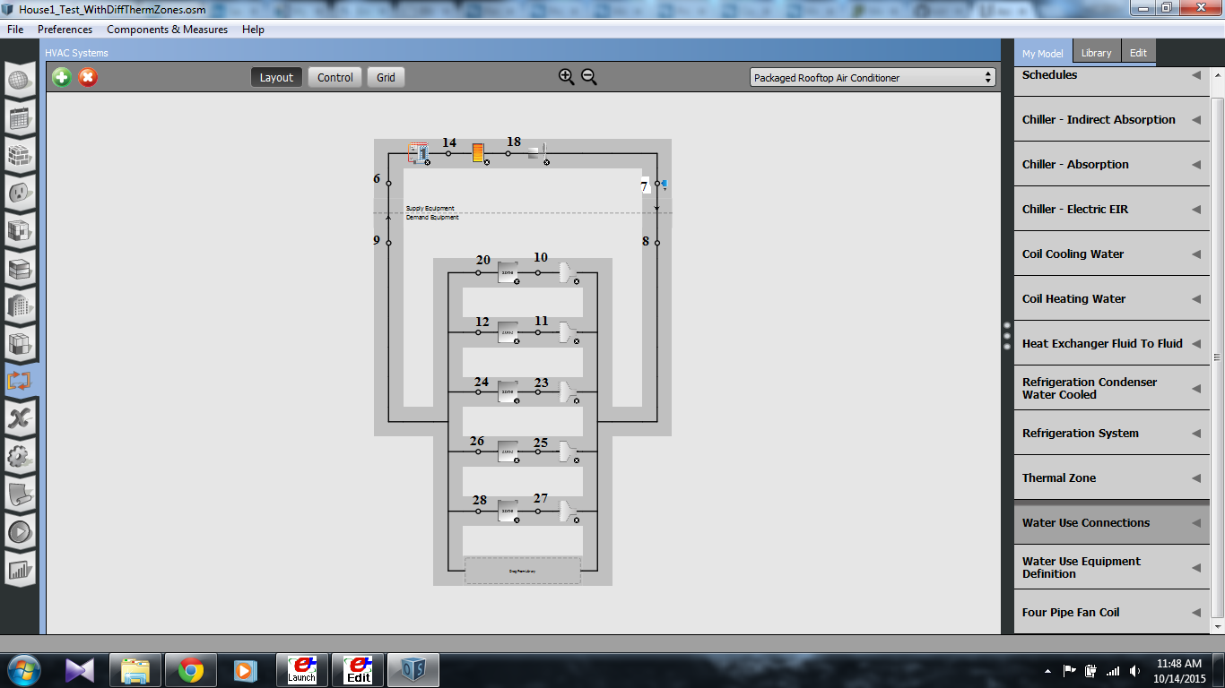
I am trying to create an Airflow Network for a House with 5 Thermal Zones, which Interact with each other. The HVAC Systems of small Houses do not use Outdoor Air Mixers but have a draft at a low height in the Controlling Thermal Zone (Living Room) to suck the air into the HVAC system and then Recirculate this air to all the other thermal zones including the control zone. The Other Zones interacts with the Control Zone through Infiltration from Doors etc. In the Figure below which if from my OpenStudio Program I have Named all the Nodes and The thermal zones are 1-5 from Top to Bottom.

HVAC Air Distribution

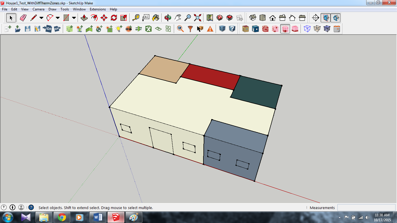
The House looks like this in SketchUp:

House Model

Here I am in a Fix as to how I should device my Airflow Network. Seems that in my Simulation Case there may not be a Air Mixer afterall The Air is directly taken from Thermal Zone 1 and then supplied to the other zones. This will make the Nodes 20 Node 9 and Node 6 Coincide. I am not sure what would be the best strategy here: Should I just create Airflow networks from Node 7 to Node 10, 11, 23, 25 and 27? and leave the system as it is or do I need to do adapt a different Strategy? Also How should I deal with the Thermostat for the controlling zone or the Set Point Manager with respect to the Air Flow Network.

SIMULATION DEFINITION

I am trying to replicate the behavior of a "low-rise" House (Single Story) which has a HVAC System catering the demand of different Rooms/Thermal Zones. Generally this HVAC System is controlled by a Thermostat Placed in the Living Room of the House, and the Set points and the Toffset of this Thermostat Governs the Switching On and Off of the HVAC System. In my Simulation in the Figure above The Control Zone is Zone-1. Moreover, the Air Flow Network in a house has a Pipe going from the Outlet of the HVAC System to different Zones/Rooms (Including the Control Thermal Zone) and there usually is no return duct. The HVAC System usually has a small (Length wise) Return Duct in the Control Thermal Zone which is used to suck the air and condition it and supply it to all the zones again. The Other Rooms/Zones interact with the Control Thermal Zone Solely Through Infiltration of door/Window Openings and hence provide a feedback or contribute to the Temperature Signal that the Control Zone Generates after each time step. I am trying to simulate Exactly This Air Flow Network. Through the GitHub Code I could Figure out regarding the Inter-zone Mixing (Zone Cross Mixing Object) but I am having troubles in putting the Duct work (Which will have no Pressure Drop) similar to what I described above. Also I am not pretty sure about the "AirTerminal:SingleDuct:Uncontrolled" objects, as to what they are exactly doing for each zone, are they a replacement ... (more)

edit retag flag offensive close merge delete

Comments

Are you asking about the EnergyPlus Airflow Network specifically, or an airlfow network in general? If the latter, I suggest rephrasing your question to avoid confusion.

MatthewSteen's avatar MatthewSteen  ( 2015-10-14 17:27:38 -0500 )edit

Hello Matthew,

Thank You for the comment. Yes I was talking about the EnergyPlus Airflow network. I am not sure what "airflow network in general" will mean vis a vis Building Energy Simulations. Can you elaborate on the difference a little?

Thank You for your time.

Nadish

nadish21's avatar nadish21  ( 2015-10-14 23:54:21 -0500 )edit

2 Answers

Sort by ยป oldest newest most voted
3

answered 2015-10-15 13:53:21 -0500

It's unclear whether you're using OpenStudio exclusively or just to generate the IDF for EnergyPlus, but here are some suggestions from the OS perspective.


ZoneMixing

ZoneMixing is not currently supported by OS through the GUI but is available through the API via an OpenStudio Measure. ZoneMixing objects could be added to your OSM prior to using one of the steps below for the AFN.


Airflow Network

As of OpenStudio 1.9.0, the EnergyPlus Airflow Network model is not supported. Two options for adding it to your model:

  1. Write an EnergyPlus Measure to add the AFN objects to your model after OS translates the model to IDF.

  2. Move to EnergyPlus to add Airflow Network objects by using the out.idf file produced by OS, which is available in the OSM directory at ...\run\4-EnergyPlusPreProcess-0.

edit flag offensive delete link more

Comments

Hello Matthew,

Thank You for the answer. I was using OpenStudio to Make IDF and then use this IDF in EnergyPlus for my simulation. I gave the OpenStudio Image to explain how my system looks. I Will update my Question with the IDF File. Although my Airflow network is Incomplete, I have tried to complete the IDF based on a GitHub Code of Airflow Network of a House. I will also post that link in my Question. I would appreciate it if you could consider my question once again with this added information.

Thank You for your time.

Sincerely,

Nadish

nadish21's avatar nadish21  ( 2015-10-15 14:16:07 -0500 )edit

@nadish21 unfortunately I don't have experience with the AFN yet ( @Jason DeGraw may be able to help). It sounds like you've got a good workflow using OpenStudio GUI to generate the IDF, but here's some further suggestions:

  1. Create and debug as much of the model as possible in the OS GUI
  2. Write an OpenStudio Measure to add the ZoneMixing objects and debug the results
  3. Move to EnergyPlus to add the AFN and final simulations
MatthewSteen's avatar MatthewSteen  ( 2015-10-15 19:13:28 -0500 )edit

Hello nadisch21, I'm using E+ airflow networks for my PhD. I don't have time today, but I will look at your idf in the weekend. Do you want the zones to be linked to eachother or only to the controlling zone? (maybe add a plan of the building) Kind regards.

BBel's avatar BBel  ( 2015-10-16 02:55:55 -0500 )edit

Hello BBel,

Thank you so much for taking time out and responding to my Queries. I am updating my Original Question with the Problem Definition, which will give the Salient Features of my simulation. This I feel will give a broader perspective towards the Problem that I am facing regarding the Air Flow Network.

Sincerely,

Nadish

nadish21's avatar nadish21  ( 2015-10-16 09:49:26 -0500 )edit
1

answered 2015-10-18 13:39:42 -0500

Hi nadish,

I think you can leave the mixer out (if E+ complains, keep it and only connect the first zone.) The airflow between the other zones and the living room can be modeled as crack flow or flow through a simple or detailed component with venting availability schedules on the surfaces of those leakage components. Are you planning to integrate user behavior? (interzone door opening/closing). I had less time than expected, so I'll have a second look at your question in the morning. Kind regards.

edit flag offensive delete link more

Comments

Hello BBel,

Thank you once again for your time. Yes I want all the Internal Doors to be open since this will somewhat ease up the zone Cross mixing. I am not sure how to model cracks. I am also not sure about where to keep the thermostat and what to do with the Pipes and Plenum's. I would be very grateful if you can shed some light on this as well. What is the topic of your PhD Research? (if you do not mind telling).

Again Thank you for all your help.

Sincerely,

Nadish

nadish21's avatar nadish21  ( 2015-10-18 14:38:44 -0500 )edit

Hi Nadish, I don't mind telling. I'm working on the optimization of a generic hybrid ventilation system (balancing user comfort, IAQ and energy-efficiency). I think you are looking at the wrong E+ example file. If you have installed E+ take a look at the following files in the installation directory C:\EnergyPlusVx-x-x\ExampleFiles --> AirflowNetwork3zVent, AirflowNetwork_MultiZone_SmallOffice and AirflowNetwork_MultiZone_House. They will help you understand the setup of the airflownetwork and the ductwork.

BBel's avatar BBel  ( 2015-10-19 03:11:27 -0500 )edit

Q: Also I am not pretty sure about the "AirTerminal:SingleDuct:Uncontrolled" objects --> A: Supplies central system air directly to a zone and only contains the zone inlet node without ducts. (=both the zone inlet node and the outlet node of the AirLoopHVAC:ZoneSplitter.)

BBel's avatar BBel  ( 2015-10-19 07:30:35 -0500 )edit

@BBel Were you ever able to model the return path as a simple opening? E+ Does not seem to like having a AFN:Multizone:Component selected where it should be a AFN:Distribution:Component. Have you had any success defining a supply terminal without the return pathway?

I currently have a house model with a detailed AFN. Each return from the zone is modeled as crack flow into the next space, however I am getting a matrix singularity error. Ideally I would not define a return object, as this does not exist in reality, the actual system has one point of return in a hallway.

spqr's avatar spqr  ( 2016-04-06 07:32:04 -0500 )edit

Hello spqr, sorry for the late answer. I was on holidays. Could you rephrase your question? I think you are mixing up the setup of an HVACairloop and an AFN. If you want air from a zone to return to a AHU I would use zone mixing objects and dummy fans instead of an AFN approach.

BBel's avatar BBel  ( 2016-04-19 03:04:47 -0500 )edit

Your Answer

Please start posting anonymously - your entry will be published after you log in or create a new account.

Add Answer

Careers

Question Tools

2 followers

Stats

Asked: 2015-10-14 11:06:03 -0500

Seen: 2,230 times

Last updated: Oct 18 '15