Creating Airflow Network for a House
Hello,
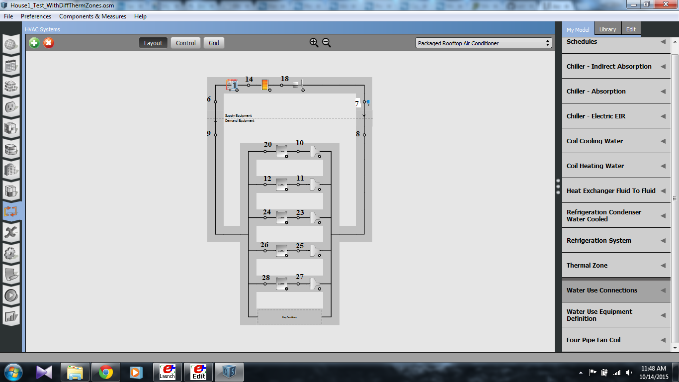
I am trying to create an Airflow Network for a House with 5 Thermal Zones, which Interact with each other. The HVAC Systems of small Houses do not use Outdoor Air Mixers but have a draft at a low height in the Controlling Thermal Zone (Living Room) to suck the air into the HVAC system and then Recirculate this air to all the other thermal zones including the control zone. The Other Zones interacts with the Control Zone through Infiltration from Doors etc. In the Figure below which if from my OpenStudio Program I have Named all the Nodes and The thermal zones are 1-5 from Top to Bottom.
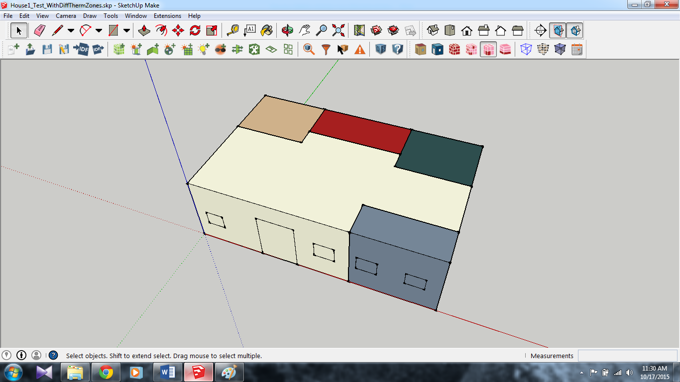
The House looks like this in SketchUp:
Here I am in a Fix as to how I should device my Airflow Network. Seems that in my Simulation Case there may not be a Air Mixer afterall The Air is directly taken from Thermal Zone 1 and then supplied to the other zones. This will make the Nodes 20 Node 9 and Node 6 Coincide. I am not sure what would be the best strategy here:
Should I just create Airflow networks from Node 7 to Node 10, 11, 23, 25 and 27? and leave the system as it is or do I need to do adapt a different Strategy? Also How should I deal with the Thermostat for the controlling zone or the Set Point Manager with respect to the Air Flow Network.
SIMULATION DEFINITION
I am trying to replicate the behavior of a "low-rise" House (Single Story) which has a HVAC System catering the demand of different Rooms/Thermal Zones. Generally this HVAC System is controlled by a Thermostat Placed in the Living Room of the House, and the Set points and the Toffset of this Thermostat Governs the Switching On and Off of the HVAC System. In my Simulation in the Figure above The Control Zone is Zone-1. Moreover, the Air Flow Network in a house has a Pipe going from the Outlet of the HVAC System to different Zones/Rooms (Including the Control Thermal Zone) and there usually is no return duct. The HVAC System usually has a small (Length wise) Return Duct in the Control Thermal Zone which is used to suck the air and condition it and supply it to all the zones again. The Other Rooms/Zones interact with the Control Thermal Zone Solely Through Infiltration of door/Window Openings and hence provide a feedback or contribute to the Temperature Signal that the Control Zone Generates after each time step. I am trying to simulate Exactly This Air Flow Network. Through the GitHub Code I could Figure out regarding the Inter-zone Mixing (Zone Cross Mixing Object) but I am having troubles in putting the Duct work (Which will have no Pressure Drop) similar to what I described above. Also I am not pretty sure about the "AirTerminal:SingleDuct:Uncontrolled" objects, as to what they are exactly doing for each zone, are they a replacement for the Ductwork or they just act like vents? Moreover, The control for the HVAC System is happening through the "SetpointManager:SingleZone:Reheat" Object (Shown at Node 7 in the above figure), where I have given the Control Zone as Thermal Zone 1. I am in a dilemma regarding the positioning of the Thermostat Control, I feel that the Thermostat Sensor must be placed at Node 20 because this position replicated the actual position of a Thermostat in a real House. I am not sure how to go about this either, since the "SetpointManager:SingleZone:Reheat" object along with providing the Thermostat Sensor also provides a control for the HVAC system by providing the Minimum and Maximum Supply Temperatures (Which will not allow the HVAC Components to work on Part Load since it will sense a very High Temperature Gap to cover, but at the same time will switch on and off according to the Thermal Zone 1 temperature and Toffset).
Added Information:
I am Using OpenStudio to Generate an IDF and not Trying to use it to make an Airflow network. The Figure above from OpenStudio Shows how my HVAC System looks Schematically. Also I am using an EPlus IDF posted on GitHub as a reference for my Airflow Network Design. Links to both EnergyPlus File and the GitHub Code is posted below.
Links to Various Files:
IDF FIle
GitHub Link
SketchUp File
I know the problem seems to be very complicated, but to perform academic level research it is imperative of me to not assume things and try to replicate exact observed behavior in my simulations. I am very grateful for the feedback of many experts here on unmet hours. It has been very helpful. I have tried to be as comprehensive as I could regarding the problem definition of my simulation and Any Help vis a vis to the problems stated therein will be greatly Appreciated.
Sincerely,
Nadish Anand


