Question-and-Answer Resource for the Building Energy Modeling Community
Get started with the Help page
Ask Your Question
9

Heating demand not passed from DHW loop to Boiler loop

asked 2015-09-22 06:24:45 -0600

updated 2015-09-22 09:00:36 -0600

I've been struggling trying to model an indirect water heater, where a Boiler:HotWater operates in constant flow, variable temperature, trying to meet a setpoint in a water tank, that in turns serves WaterUse:Connections.

Short story

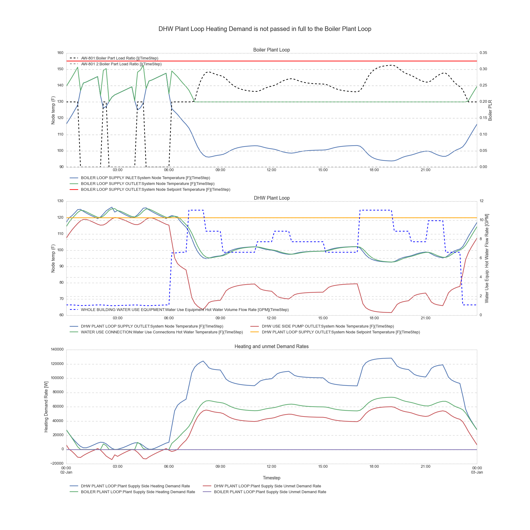
it seems that I cannot get the DHW loop (secondary) to pass its demand back to the Boiler loop (primary). Below is a graph (click on it for enlarged version) of what I'm experiencing: the DHW loop temps are NOT satisfactory, while I'm only at 30% capacity of one of my two boilers... There is Unmet Demand Rate on my DHW loop but not on my Boiler Loop.

Click for enlarged

Here is my IDF file


Details

In reality

Piping arangement

This is a primary/secondary loop arrangement. The boiler has a dedicated boiler pump, ON/OFF, constant flow, interlocked with boiler operation (typically, the pump actually starts before the boiler, and a flow switch will allow the boiler so start its ignition sequence).

The boiler feeds the tank via an internal heat exchanger: the boiler water is in the heat exchanger tubing (I guess this means source side effectiveness < 1) that is sitting in the Service Hot Water (Use Side effectiveness = 1)

The DHW loop has a recirculation pump for priming purposes only (keeping the loop at temperature to avoid drawing cold water for minutes during low load), typically only a fractional pump (less than 1HP) moving about 1 GPM per 20 fixtures (rule of thumb, ASHRAE Handbook of Fundamentals 2011, Chapter 50). It's the cold water pushing in that really moves the fluid when there's a draw on the DHW loop (from city mains pressure for low rise buildings, or for high-rise a gravity tank, booster pumps...)

There's usually a mixing valve after the tank to temper the DHW to a reasonable level, say about 120°F.

Control Sequence

There is an aquastat in the water tank that is the main variable controlling the boiler. Here is the control sequence as I understand it:

  • The boiler has a Setpoint, an offset and a differential. Typical values are respectively 125°F, 5°F, and 5°F
  • The boiler cut-off is at Setpoint+Offset. Typical value: 130°F. (Read: if tank reaches 130°F, boiler cuts off)
  • The boiler cut-in is at Setpoint-Differential. Typical value: 120°F
  • In between, the firing rate is adjusted by PID control to meet the tank setpoint.
  • There are additional settings such as anti-cycle (a delay in minutes to prevent short cycling) that I'm not concerned with yet.

In EnergyPlus / Efforts so far

Plant Loops

Here is the drawing of the loop as I understand it:
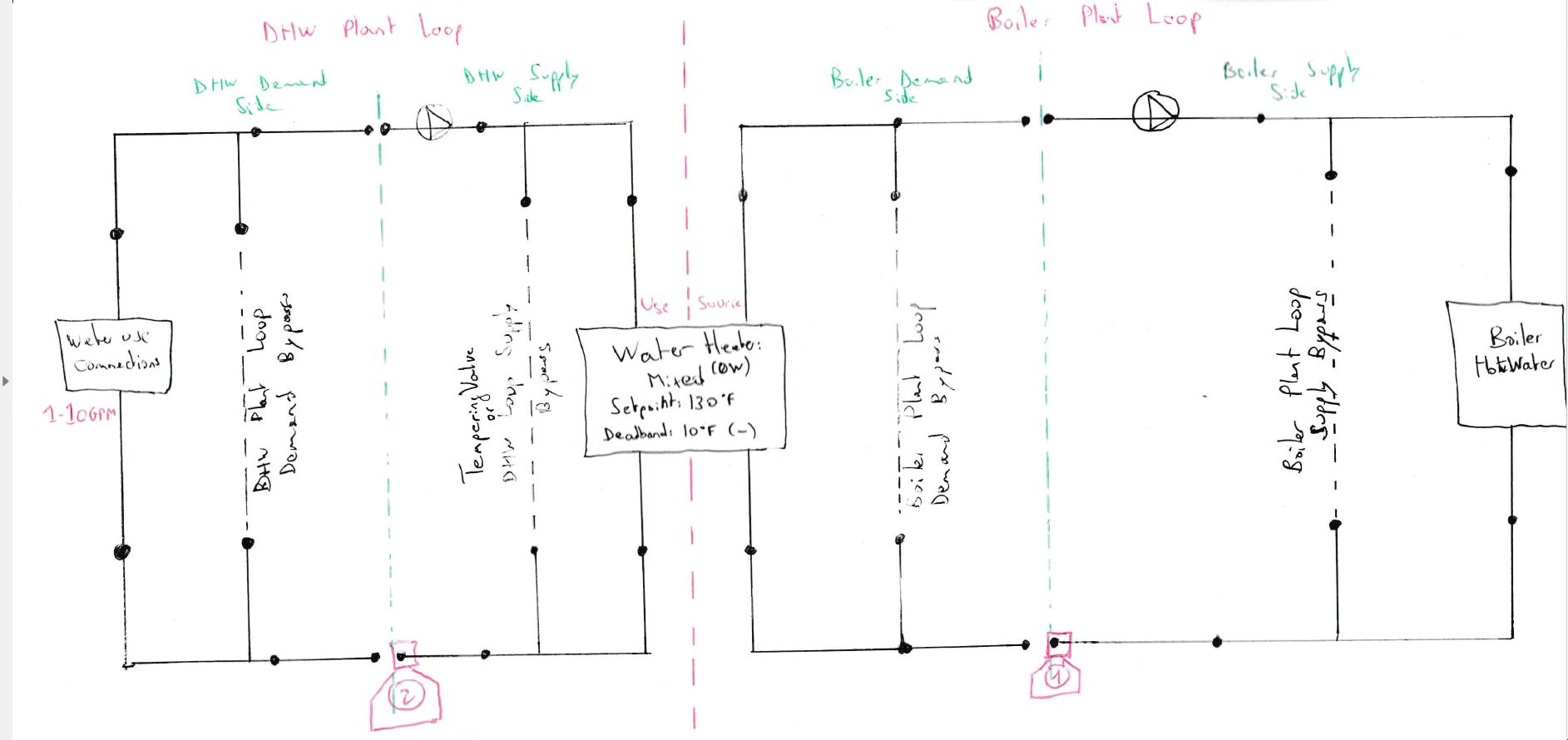
image description

  • The boiler pump is a Pump:ConstantSpeed while the DHW pump is a Pump:VariableSpeed with a minimum flow rate corresponding to the recirculation rate (technically only the recirculation rate should have an electric consumption here, but I'm not going to care).
  • The boiler is a Boiler:HotWater.
  • The storage tank is a WaterHeater:Mixed with zero ...
(more)
edit retag flag offensive close merge delete

3 Answers

Sort by » oldest newest most voted
8

answered 2015-09-29 09:53:06 -0600

updated 2015-10-16 11:21:57 -0600

There isn't a setpoint manager that will adjust a PlantLoop temperature setpoint based on it's load (that I'm aware of). There are air system setpoints that do something similar, but you may need to program a SetpointManager:Scheduled with an EMS actuated schedule to mimic a similar control of your boiler loop.

You can use the Water Heater Tank Temperature, $T_{tank}$, to represent the reading from the aquastat. You can approximate perfect PID control by using the Water Heater Total Demand Heat Transfer Rate, $\dot{Q}_{demand}$, the mass flow rate of your boiler loop, $\dot{m}$, and the Source Side Effectiveness, $\varepsilon$, to calculate the required setpoint temperature:

$$T_{set} = T_{tank} + \frac{\dot{Q}_{demand}}{\varepsilon \cdot \dot{m}\cdot C_p}$$

edit flag offensive delete link more

Comments

I haven't tried it yet, but I'm going to. Seems weird that there doesn't seem to be a way to do a constant flow variable temperature plant loop..

Julien Marrec's avatar Julien Marrec  ( 2015-10-02 18:22:45 -0600 )edit
1

User-voice request for constnat flow variable temperature plant loops here

Julien Marrec's avatar Julien Marrec  ( 2015-10-16 06:55:54 -0600 )edit

@Neal Kruis, effectiveness should be at the denominator. Also, I couldn't make it work with Water Heater Total Demand Heat Transfer Rate. Using Water Heater Unmet Demand Heat Transfer Rate seems to have worked better though.

Julien Marrec's avatar Julien Marrec  ( 2015-10-16 10:02:45 -0600 )edit
4

answered 2015-09-22 11:01:41 -0600

Archmage's avatar

Here are some things I would check.

You are autosizing the tank's source side and plant loop design flow rate, but hard sizing the boiler flow rates -- make sure these are coming out to be consistent.

At first glance it seemed like maybe the tank's source side flow rate is too low, you could try a shorter indirect heat recovery time.

The design water outlet temperature in the boilers is set at 48.9C, I think you want this match the 82.22 setpoint for the boiler loop.

I am not sure you really need DualSetpointDeadband in the boiler plant loop, you might try using single setpoint there.

edit flag offensive delete link more

Comments

Thanks for you answer. I actually want the boiler to be constant flow, variable temperature, between 130°F and 180°F. I'd ideally like if E+ could calculate what's the lowest temperature I need to satisfy the tank. I think your rationale about tank source side flow rate being too low is really good though, I'm going to check that.

Julien Marrec's avatar Julien Marrec  ( 2015-09-22 11:13:03 -0600 )edit

Hum the tank source side flow is equal to my boiler loop maximum flow.

Julien Marrec's avatar Julien Marrec  ( 2015-09-22 11:14:14 -0600 )edit

The boiler loop is being sized to match that, so they should be equal. But how does that compare to the sum of the two boiler's hard size. If the boilers were too small, then much of the flow would go around them.

Archmage's avatar Archmage  ( 2015-09-22 11:22:58 -0600 )edit

The boiler flows and capacity are from manufacturer data, so they match. Ultimately, I don't understand why the temperature of the boiler loop doesn't just go up between 130°F and 180°F to match the demand? Also why the DHW loop has 'Unmet demand' while the boiler loop doesn't?

Julien Marrec's avatar Julien Marrec  ( 2015-09-22 12:04:06 -0600 )edit
1

answered 2015-09-30 15:07:41 -0600

I've come across a similar situation trying to only allow flow in a radiant panel for specific temperature ranges. What I found is that if I replaced my AvailabilityManager:HighTemperatureTurnOff objects (which turn plant loops OFF when a sensor node is ABOVE a specific temperature) to AvailabilityManager:LowTemperatureTurnOn objects (which turn plant loops ON when a sensor node is BELOW a specific temperature), then it operated as desired.

In general, each System Availability Manager object in E+ has a "Control Status" output variable. The values indicate whether the Availability Manager is telling the Plant loop to 'Force Off', 'Cycle On', or 'No Action'. Precedence for controlling the loop also follows that order: if ANY component on the plant loop has an availability manager that reports 'Force Off', then the entire plant loop will be forced off.

edit flag offensive delete link more

Your Answer

Please start posting anonymously - your entry will be published after you log in or create a new account.

Add Answer

Training Workshops

Careers

Question Tools

2 followers

Stats

Asked: 2015-09-22 06:24:45 -0600

Seen: 1,457 times

Last updated: Oct 16 '15