I've been struggling trying to model an indirect water heater, where a Boiler:HotWater operates in constant flow, variable temperature flow, trying to meet a setpoint in a water tank, that it turns serves WaterUse:Connections.
Short story
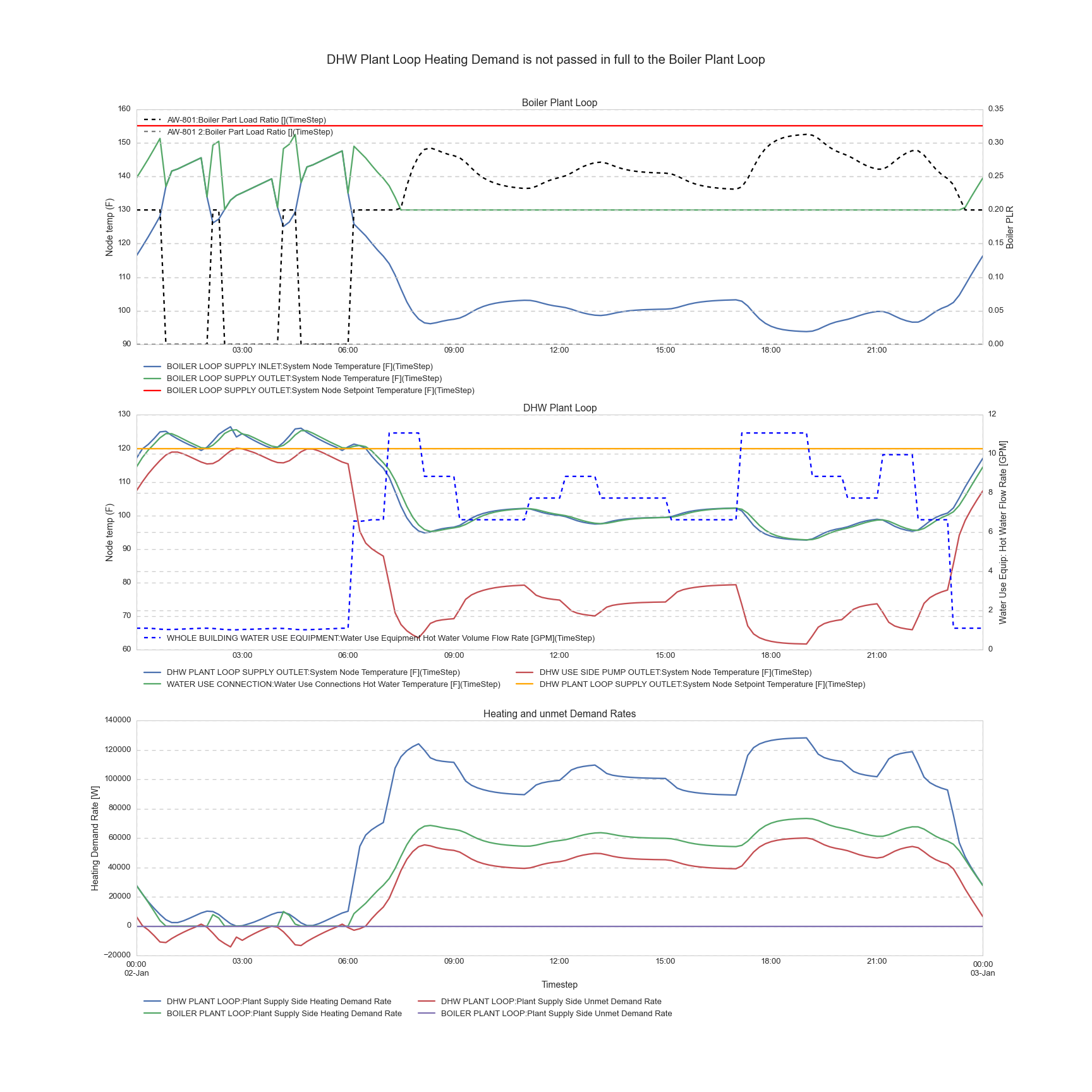
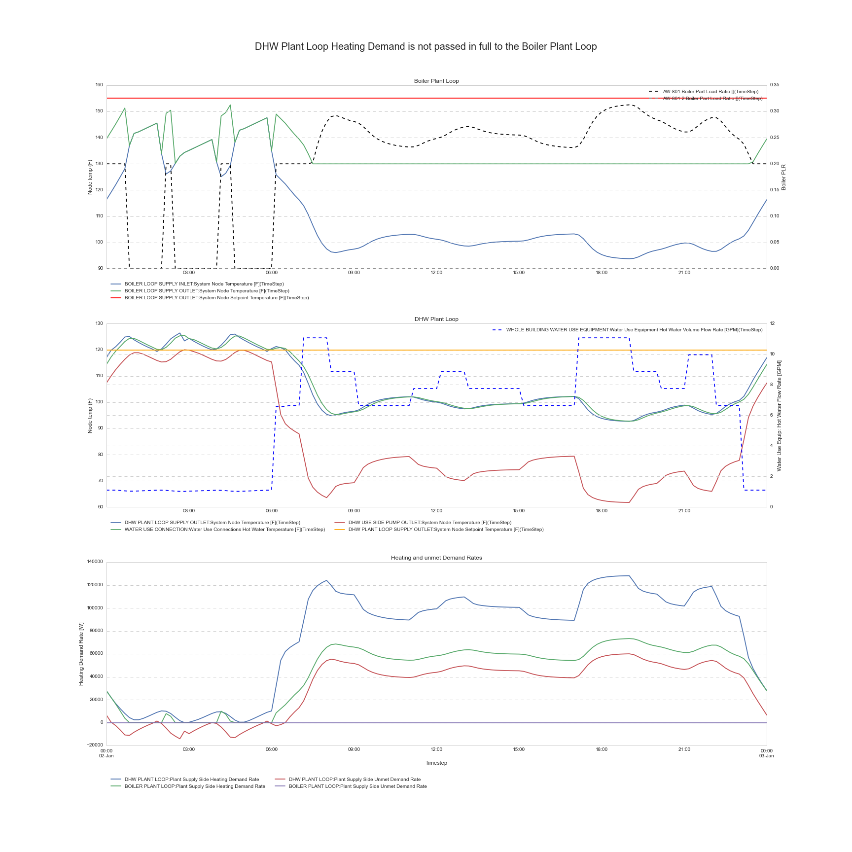
it seems that I cannot get the DHW loop (secondary) to pass its demand back to the Boiler loop (primary). Below is a graph (click on it for enlarged version) of what I'm experiencing: the DHW loop temps are NOT satisfactory, while I'm only at 30% capacity of one of my two boilers... There is Unmet Demand Rate on my DHW loop but not on my Boiler Loop.
Here is my IDF file
Details
In reality
Piping arangement
This is a primary/secondary loop arrangement. The boiler has a dedicated boiler pump, ON/OFF, constant flow, interlocked with boiler operation (typically, the pump actually starts before the boiler, and a flow switch will allow the boiler so start its ignition sequence).
The boiler feeds the tank via an internal heat exchanger: the boiler water is in the heat exchanger tubing, the rest of the tank is Service Hot Water.
The DHW loop has a recirculation pump for priming purposes only (keeping the loop at temperature to avoid drawing cold water for minutes during low load), typically only a fractional pump (less than 1HP) moving about 1 GPM per 20 fixtures (rule of thumb, ASHRAE Handbook of Fundamentals Chapter 14). It's the cold water pushing in that really moves the fluid when there's a draw on the DHW loop (from city mains pressure for low rise buildings, or for high-rise a gravity tank, booster pumps...)
There's usually a mixing valve after the tank to temper the DHW to a reasonable level, say about 120°F.
Control Sequence
There is an aquastat in the water tank that is the main variable controlling the boiler. Here is the control sequence as I understand it:
- The boiler has a Setpoint, an offset and a differential. Typical values are respectively 125°F, 5°F, and 5°F
- The boiler cut-off is at Setpoint+Offset. Typical value: 130°F. (Read: if tank reaches 130°F, boiler cuts off)
- The boiler cut-in is at Setpoint-Differential. Typical value: 120°F
- In between, the firing rate is adjusted by PID control to meet the tank setpoint.
- There are additional settings such as anti-cycle (a delay in minutes to prevent short cycling) that I'm not concerned with yet.
In EnergyPlus / Efforts so far
Plant Loops
Here is the drawing of the loop as I understand it:
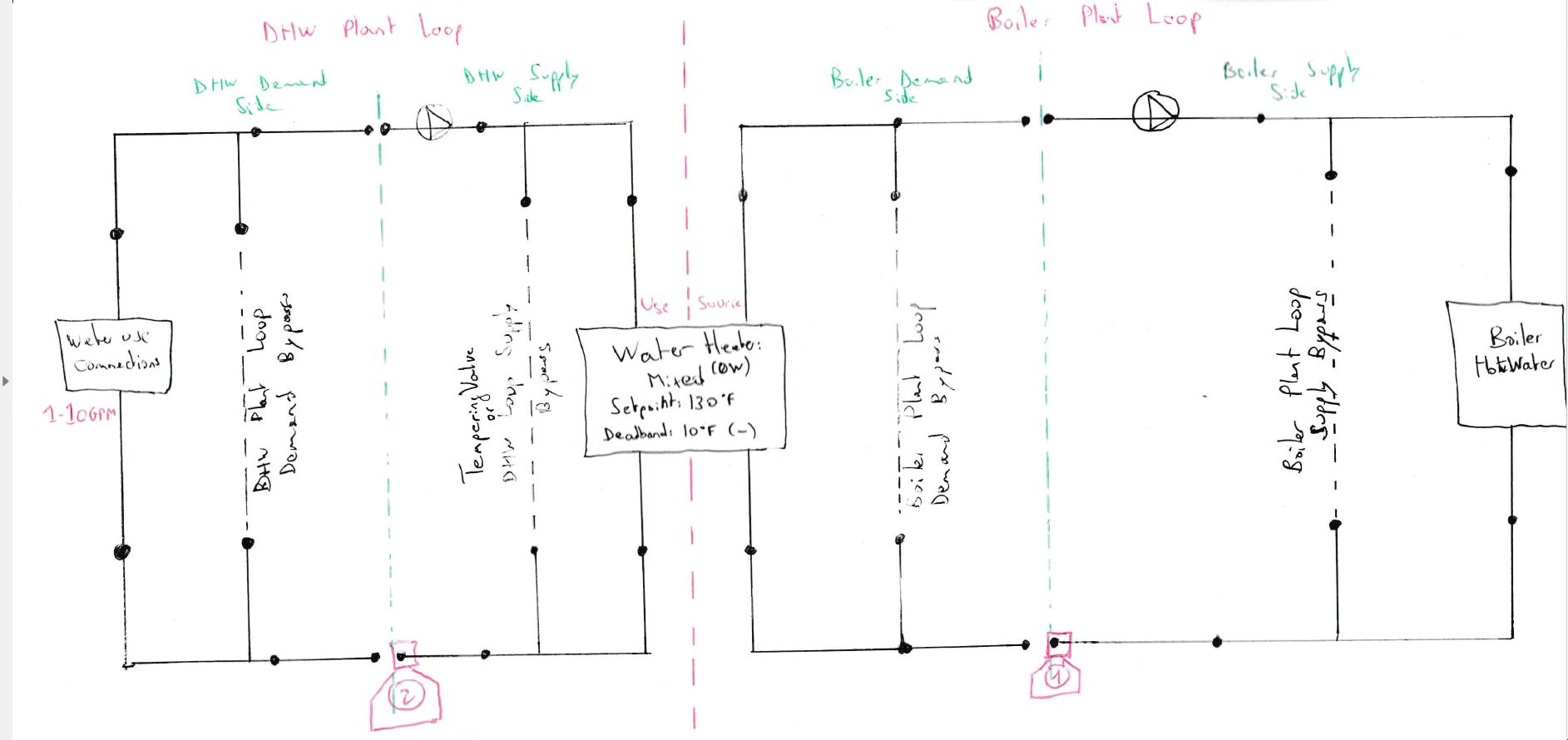
- The boiler pump is a
Pump:ConstantSpeedwhile the DHW pump is aPump:VariableSpeedwith a minimum flow rate corresponding to the recirculation rate (technically only the recirculation rate should have an electric consumption here, but I'm not going to care). - The boiler is a
Boiler:HotWater. - The storage tank is a
WaterHeater:Mixedwith zero capacity, set to have a Setpoint of 130°F and a deadband of 10°F, and set to have a Source Side Flow Control Mode ofIndirectHeatPrimarySetpoint
Controls
My initial thoughts:
- The Water Use Connection has a target temp of 120°F (doesn't really matter)
- The DHW Plant Loop has a
SetpointManager:Scheduledof 120°F on theDHW Plant Loop Supply Outlet - The
Boiler Plant Loopshould have aSetpointManager:DualSetpointwith a low of 130°F and a high of 180°F on the Boiler Plant Loop Supply Outlet. The PlantLoop should have a 'Plant Demand Calculation Scheme of Dual Setpoint' - The Boiler Plant Loop should have two availability managers: an
AvailabilityManager:HighTemperatureTurnOffand anAvailabilityManager:LowTemperatureTurnOnboth set to theStorage Tank Use Outlet Nodewith respective values of 130°F (cut-off) or 120°F (cut-in)
Problem:
I can get the DHW loop (secondary) to pass on its load requirements to the Boiler loop (primary), as shown in the graph at the beginning of this post. I was expecting the boiler loop to vary the temperature coming out of the boilers so that the tank gets heated enough, but it doesn't.
Efforts: Well, I've tried pretty much everything. Hard sizing equipment capacities, flow rates, changing setpoints, etc. The only way I can get it to work is to put only a scheduled setpoint on the boiler supply side set to a constant 180°F, but this is definitely not what I want.
Can someone help me?