Is this the correct configuration for my HVAC system?
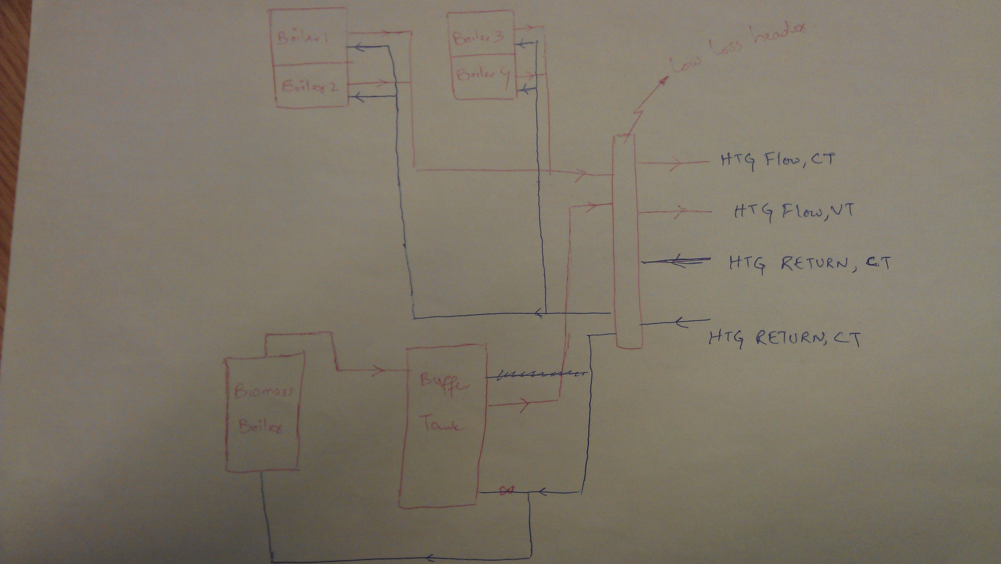
I am modelling a system in E+, the actual system consists of a biomass and 4 gas boilers. The biomass boiler is connected to the buffer tank, whereas the gas boilers heats up the fluid through a low mass header. There are two circuits; one is constant temperature (serving AHUs and underfloor heating) and the second is variable temperature circuit (serving radiant panels around the buildings). Schematic of actual system is here;

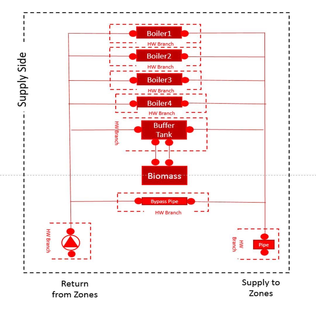
The way I am approaching it is shown in E+ schematic at the end of the question. I am just wondering, is the schematic right configuration for the system or I am missing something? The location of splitters, mixers pumps, heat exchanger is correct or not? I divided both constant and variable temperature circuits by using two heat exchangers.
Also, how can I set-up variable and constant flow temperatures (by using set-point managers?). Any ideas?
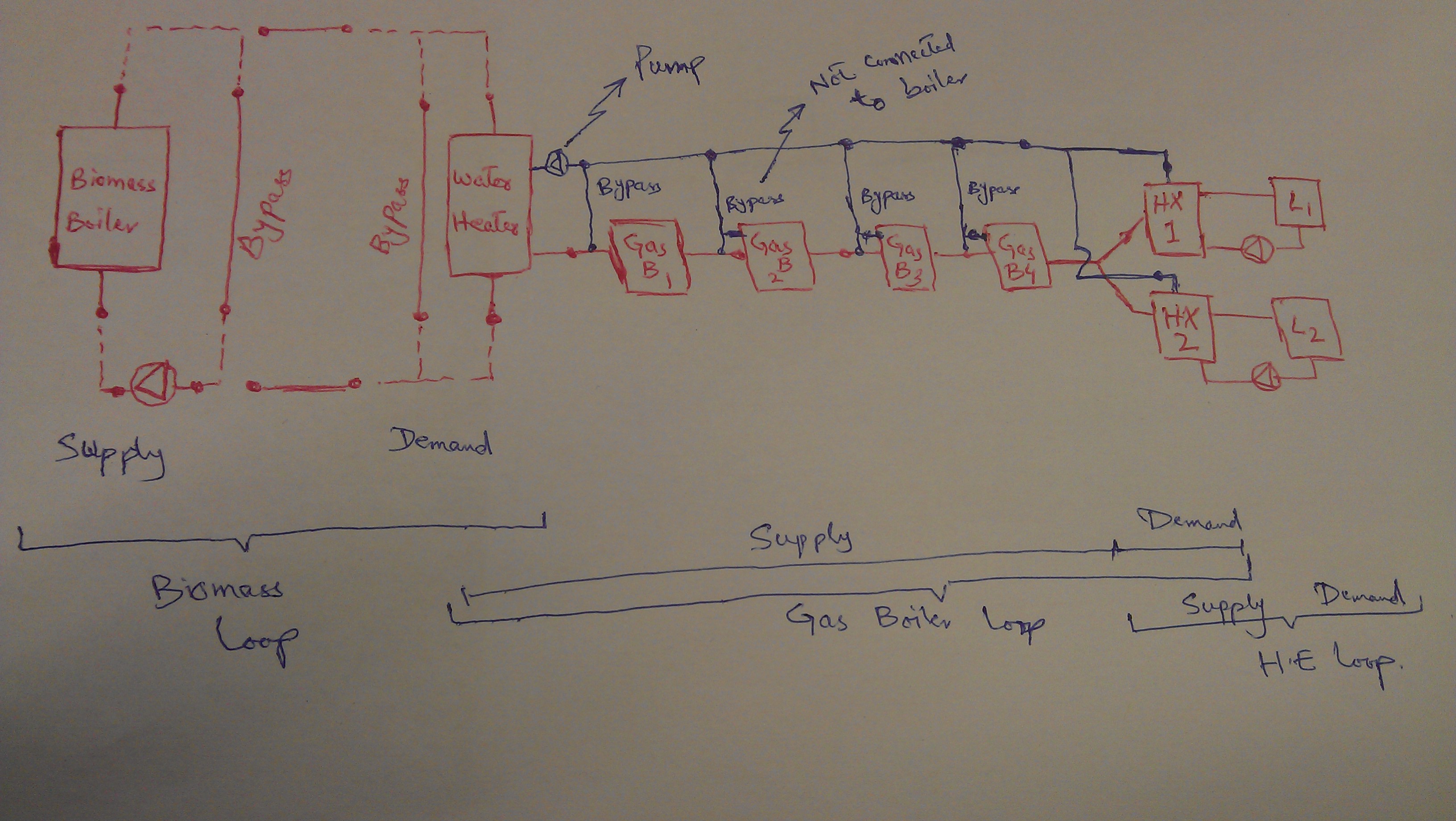
Edited schematic below!


@Waseem - can you color code each EnergyPlus Loop in your schematic? Keep in mind that you can only have one splitter and one mixer on the supply side of each loop, and one splitter and one mixer on the demand side of each loop. I can see a couple places in your schematic that violates this rule.
@kwalkerman: I have added at the end of my question that Splitter are in GREY color and Mixer are in ORANGE color, pumps are in light blue. If it violets the rule, then how can I configure my system, any ideas?