Question-and-Answer Resource for the Building Energy Modeling Community
Get started with the Help page
Ask Your Question
3

Is this the correct configuration for my HVAC system?

asked 2015-08-25 10:18:12 -0500

Waseem's avatar

updated 2015-11-12 15:39:39 -0500

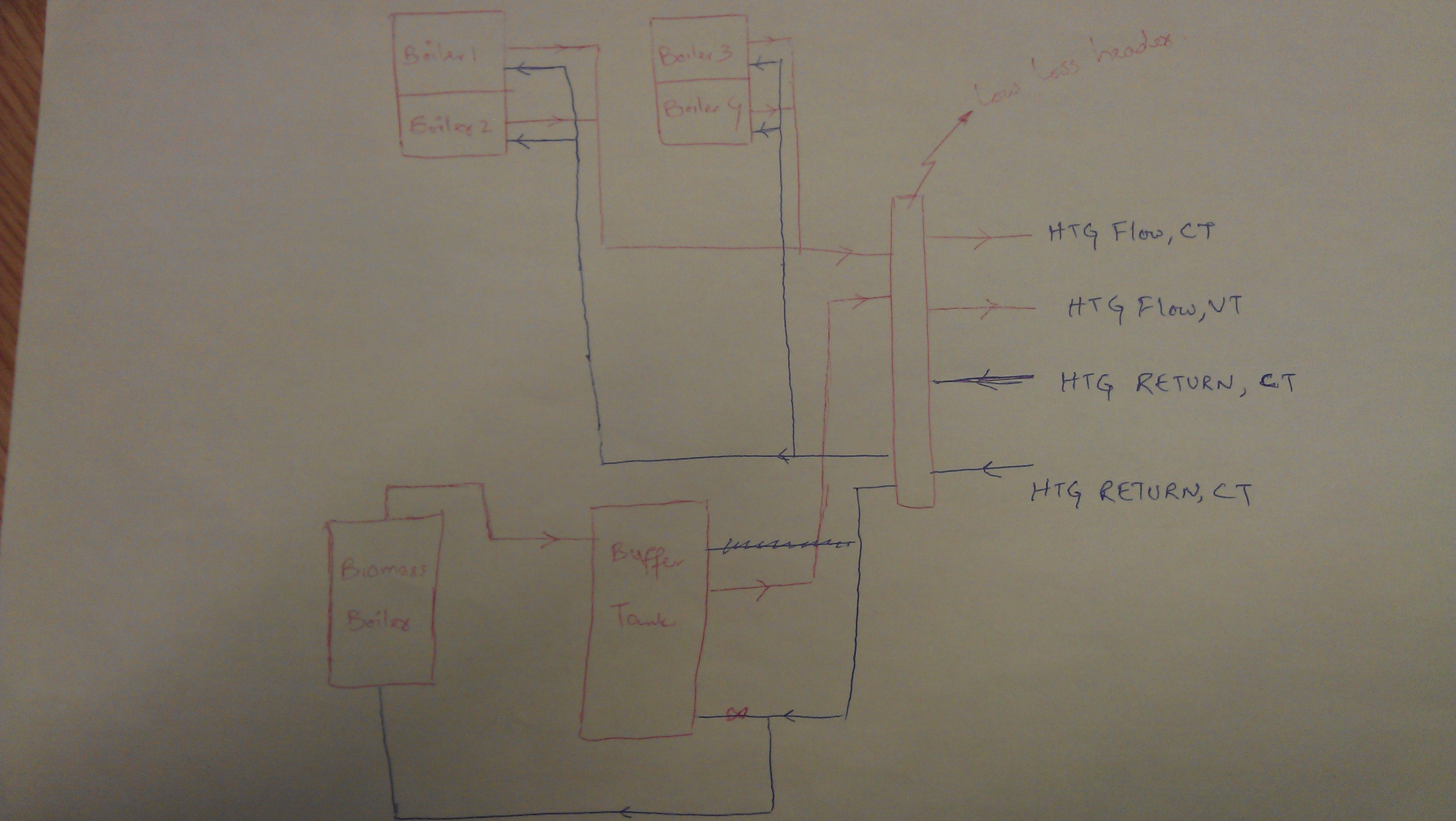
I am modelling a system in E+, the actual system consists of a biomass and 4 gas boilers. The biomass boiler is connected to the buffer tank, whereas the gas boilers heats up the fluid through a low mass header. There are two circuits; one is constant temperature (serving AHUs and underfloor heating) and the second is variable temperature circuit (serving radiant panels around the buildings). Schematic of actual system is here;

Actual system

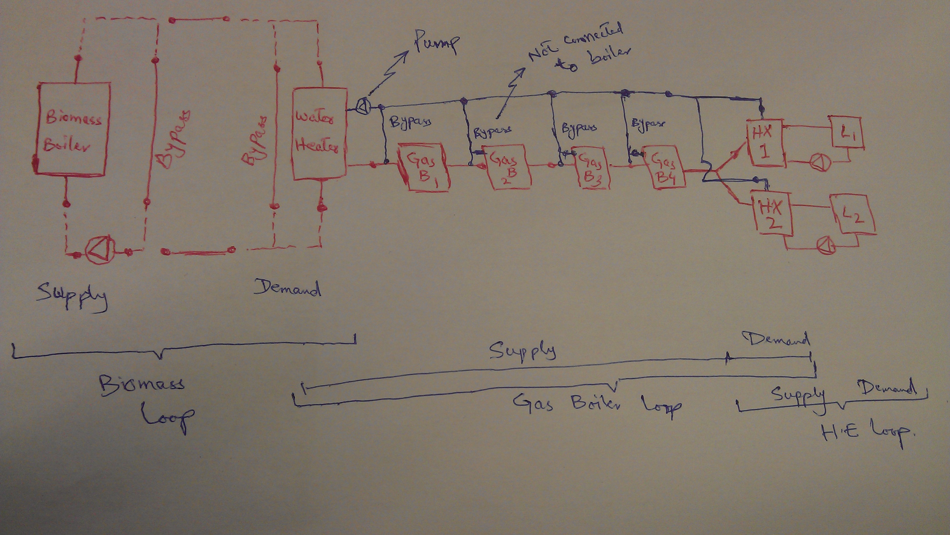
The way I am approaching it is shown in E+ schematic at the end of the question. I am just wondering, is the schematic right configuration for the system or I am missing something? The location of splitters, mixers pumps, heat exchanger is correct or not? I divided both constant and variable temperature circuits by using two heat exchangers.

Also, how can I set-up variable and constant flow temperatures (by using set-point managers?). Any ideas?

Edited schematic below!

E+ Schematic

edit retag flag offensive close merge delete

Comments

@Waseem - can you color code each EnergyPlus Loop in your schematic? Keep in mind that you can only have one splitter and one mixer on the supply side of each loop, and one splitter and one mixer on the demand side of each loop. I can see a couple places in your schematic that violates this rule.

kwalkerman's avatar kwalkerman  ( 2015-08-25 10:47:18 -0500 )edit

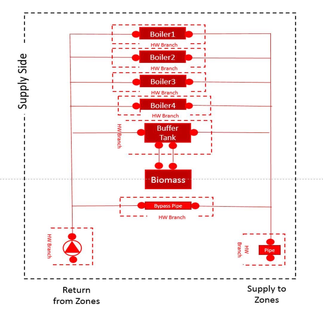
@kwalkerman: I have added at the end of my question that Splitter are in GREY color and Mixer are in ORANGE color, pumps are in light blue. If it violets the rule, then how can I configure my system, any ideas?

Waseem's avatar Waseem  ( 2015-08-25 10:51:08 -0500 )edit

1 Answer

Sort by ยป oldest newest most voted
3

answered 2015-08-25 10:52:04 -0500

updated 2015-08-25 13:31:47 -0500

Hi, here is how I would draw your plant loop in terms of EnergyPlus, I haven't included the heat exchangers because I am not sure how that would work right now, but I thought this would be a start. In EnergyPlus it is always good to look at things in loops. I find once the basics are done the more complicated parts of the system can be modelled.

image description

(updated due to @MJWitte comment below)

The bypass pipe should be connected too. I just forgot to draw the line. You can add more pumps and put them where they need to be, I just wanted to start with the basic loop.

edit flag offensive delete link more

Comments

@Annie Marston: Thanks for this. Any idea how you can separate both constant flow and variable circuits (that's why I used Heat Exchanger)?

Waseem's avatar Waseem  ( 2015-08-25 10:54:36 -0500 )edit
1

@Waseem Annie's answer covers the supply side of things. For your variable and constant temperature demand loops, put two heat exchangers in parallel on the demand side of this loop. Then make two more plant loops using the heat exchangers as the supply component. It looks like this is what you have in your diagram. I also think the supply loop above from @Annie Marston needs to have only the "use side" of the hot water tank and the biomass boiler and "source side" of the hot water tank need to be in a separate plant loop.

MJWitte's avatar MJWitte  ( 2015-08-25 11:18:22 -0500 )edit

@MJWitte: Thanks for your help. Could you please explain what you meant by "needs to have only the "use side" of the hot water tank and the biomass boiler and "source side" of the hot water tank need to be in a separate plant loop."?

Waseem's avatar Waseem  ( 2015-08-25 12:38:37 -0500 )edit

I edited the diagram above, the buffer tank actually has 4 nodes, two on the use side to connect to your main loop and 2 on the source side to connect to your biomass boiler.

Annie Marston's avatar Annie Marston  ( 2015-08-25 13:30:53 -0500 )edit

Hi @Annie Marston and @MJWitte: Thanks for your help. I have changed the schematic (in question). I have three loops now i.e. Biomass, gas boiler and HX loops. Is this the right schematic for whole system or I am missing something? Are the bypass pipes in correct position along with the pumps? Thanks again.

Waseem's avatar Waseem  ( 2015-08-26 08:38:55 -0500 )edit

Your Answer

Please start posting anonymously - your entry will be published after you log in or create a new account.

Add Answer

Careers

Question Tools

2 followers

Stats

Asked: 2015-08-25 10:18:12 -0500

Seen: 300 times

Last updated: Aug 26 '15