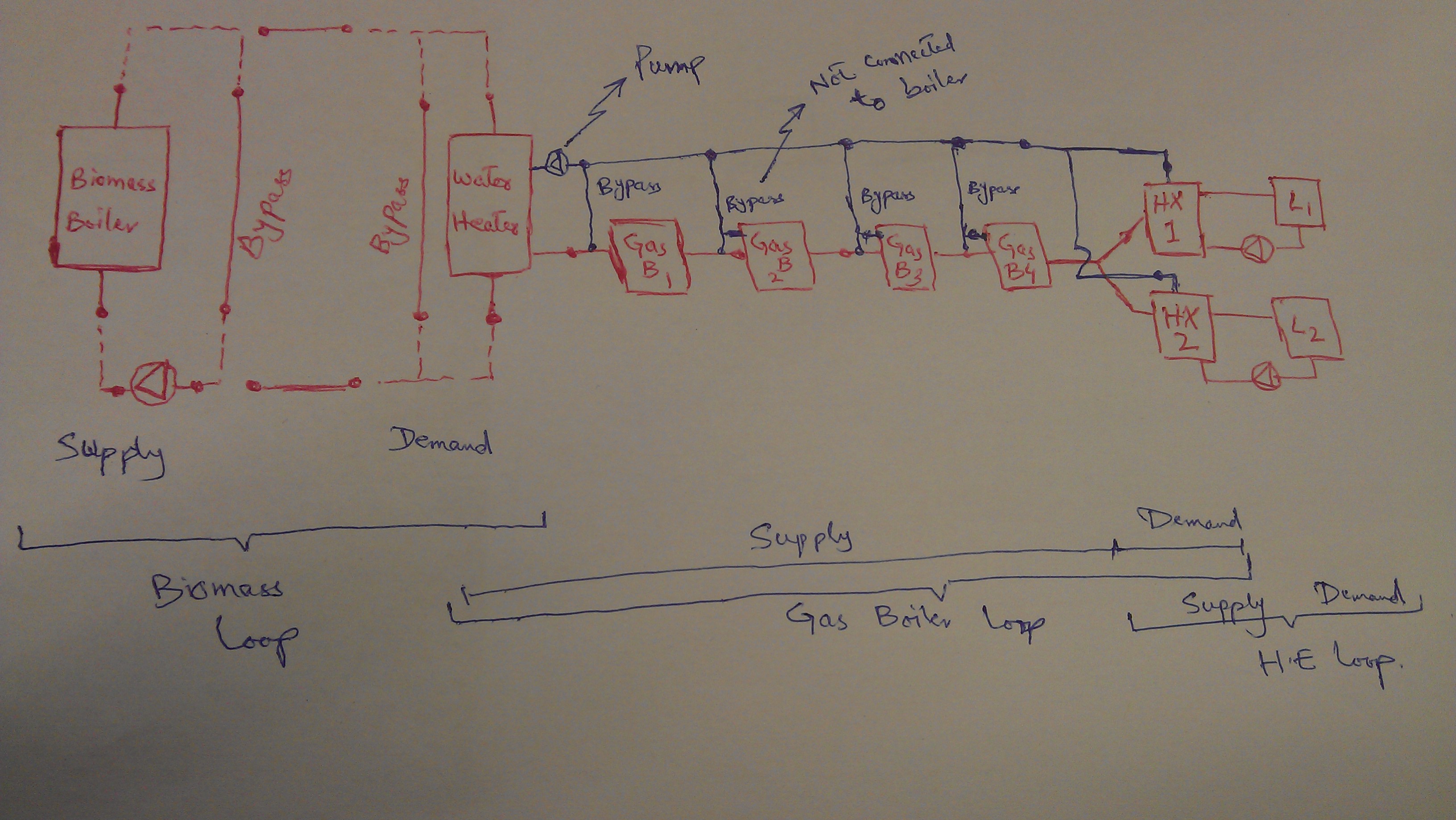
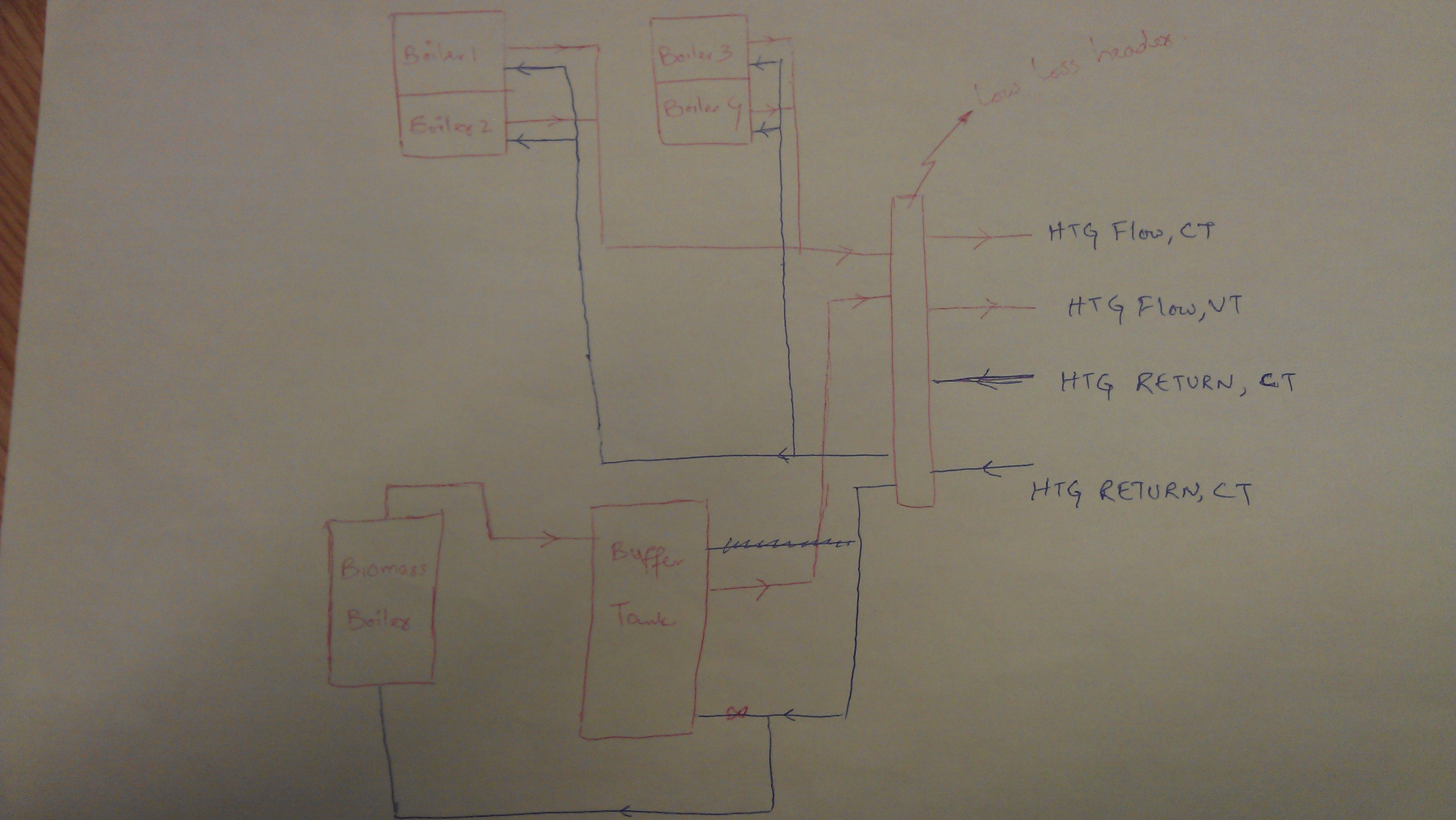
I am modelling a system in E+, the actual system consists of a biomass and 4 gas boilers. The biomass boiler is connected to the buffer tank, whereas the gas boilers heats up the fluid through a low mass header. There are two circuits; one is constant temperature (serving AHUs and underfloor heating) and the second is variable temperature circuit (serving radiant panels around the buildings). Schematic of actual system is here;
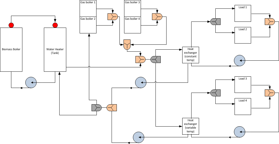
The way I am approaching it is shown in E+ schematic at the end of the question. I am just wondering, is the schematic right configuration for the system or I am missing something? The location of splitters, mixers pumps, heat exchanger is correct or not? I divided both constant and variable temperature circuits by using two heat exchangers.
Also, how can I set-up variable and constant flow temperatures (by using set-point managers?). Any ideas?
P.S: Splitters are in grey and mixers are in orange colors (kind of :)).