Question-and-Answer Resource for the Building Energy Modeling Community
| | 1 | initial version |
For V8.7.0, ZoneHVAC:LowTemperatureRadiant:VariableFlow has an input field Heating Control Throttling Range. In your case, Temperature Control Type should be MeanAirTemperature, Heating Control Temperature Schedule should be "20", and Heating Control Throttling Range should be set to "2".
but in the first place, you should use the latest version of EnergyPlus. Old versions have so many bugs and lack many new features.
| | 2 | No.2 Revision |
For V8.7.0, ZoneHVAC:LowTemperatureRadiant:VariableFlow has an input field Heating Control Throttling Range. In your case, Temperature Control Type should be MeanAirTemperature, Heating Control Temperature Schedule should be "20", and Heating Control Throttling Range should be set to "2".
but in the first place, you should use the latest version of EnergyPlus. Old versions have so many bugs and lack many new features.
UPDATE
My answer above was wrong. Sorry about that. The setting above varies the hot water flow rate from 0kg/s at 21°C to the maximum flow rate at 19°C linearly.
Alternatively, you can use EMS to model a setband. I modelled with an ExampleFile RadLoTempHydrCtrlOpt.idf (V9-4-0). The revised idf file is here.
The ExampleFile has 3 zones with ZoneHVAC:LowTemperatureRadiant:VariableFlow. I added a simle code to override the heating setpoint for West Zone. Please find the following, especially EnergyManagementSystem:Program.
Schedule:Compact,
    RADIANT HEATING SETPOINTS,  !- Name
    TEMPERATURE,             !- Schedule Type Limits Name
    Through: 12/31,          !- Field 1
    For: Alldays,            !- Field 2
    Until: 24:00,            !- Field 3
     19;                     !- Field 4

ZoneHVAC:LowTemperatureRadiant:VariableFlow,
    West Zone Radiant Floor, !- Name
    RadiantSysAvailSched,    !- Availability Schedule Name
    West Zone,               !- Zone Name
    Zn001:Flr001,            !- Surface Name or Radiant Surface Group Name
    ConvectionOnly,          !- Fluid to Radiant Surface Heat Transfer Model
    0.012,                   !- Hydronic Tubing Inside Diameter {m}
    0.016,                   !- Hydronic Tubing Outside Diameter {m}
    autosize,                !- Hydronic Tubing Length {m}
    0.35,                    !- Hydronic Tubing Conductivity {W/m-K}
    MeanAirTemperature,      !- Temperature Control Type
    ZeroFlowPower,           !- Setpoint Control Type
    HeatingDesignCapacity,   !- Heating Design Capacity Method
    Autosize,                !- Heating Design Capacity {W}
    ,                        !- Heating Design Capacity Per Floor Area {W/m2}
    ,                        !- Fraction of Autosized Heating Design Capacity
    0.00008,                 !- Maximum Hot Water Flow {m3/s}
    West Zone Radiant Water Inlet Node,  !- Heating Water Inlet Node Name
    West Zone Radiant Water Outlet Node,  !- Heating Water Outlet Node Name
    0,                       !- Heating Control Throttling Range {deltaC}
    Radiant Heating Setpoints,  !- Heating Control Temperature Schedule Name
    CoolingDesignCapacity,   !- Cooling Design Capacity Method
    Autosize,                !- Cooling Design Capacity {W}
    ,                        !- Cooling Design Capacity Per Floor Area {W/m2}
    ,                        !- Fraction of Autosized Cooling Design Capacity
    0.0012,                  !- Maximum Cold Water Flow {m3/s}
    Zone 1 Cooling Water Inlet Node,  !- Cooling Water Inlet Node Name
    Zone 1 Cooling Water Outlet Node,  !- Cooling Water Outlet Node Name
    2.0,                     !- Cooling Control Throttling Range {deltaC}
    Radiant Cooling Setpoints,  !- Cooling Control Temperature Schedule Name
    ,                        !- Condensation Control Type
    ,                        !- Condensation Control Dewpoint Offset {C}
    ,                        !- Number of Circuits
    ;                        !- Circuit Length {m}

EnergyManagementSystem:Sensor,
    MAT_West_Zone,           !- Name
    West Zone,               !- Output:Variable or Output:Meter Index Key Name
    Zone Mean Air Temperature;  !- Output:Variable or Output:Meter Name

EnergyManagementSystem:Actuator,
    Rad_Heating_SP,          !- Name
    RADIANT HEATING SETPOINTS,  !- Actuated Component Unique Name
    Schedule:Compact,        !- Actuated Component Type
    Schedule Value;          !- Actuated Component Control Type

EnergyManagementSystem:ProgramCallingManager,
    EMS_PCM_Rad_Heating_SP_Override,  !- Name
    InsideHVACSystemIterationLoop,  !- EnergyPlus Model Calling Point
    EMS_Program_Rad_Heating_SP_Override;  !- Program Name 1

EnergyManagementSystem:Program,
    EMS_Program_Rad_Heating_SP_Override,  !- Name
    IF MAT_West_Zone <= 19,  !- Program Line 1
    SET Rad_Heating_SP = 21, !- Program Line 2
    ELSEIF MAT_West_Zone >= 21,  !- A4
    SET Rad_Heating_SP = 19, !- A5
    ENDIF;                   !- A6

Output:EnergyManagementSystem,
    Verbose,                 !- Actuator Availability Dictionary Reporting
    Verbose,                 !- Internal Variable Availability Dictionary Reporting
    ErrorsOnly;              !- EMS Runtime Language Debug Output Level
The timestep result for Jan 1 to 3 is as follows.
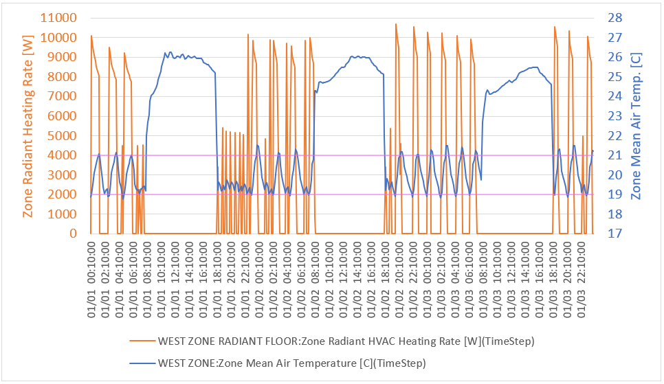
Heating Control Throttling Range in ZoneHVAC:LowTemperatureRadiant:VariableFlow needs to be set to "0". The reason why I used V9-4-0 is that the minimum value that can be input is 0.5 in older versions. V9-4-0 or newer versions allow 0.
| | 3 | No.3 Revision |
For V8.7.0, ZoneHVAC:LowTemperatureRadiant:VariableFlow has an input field Heating Control Throttling Range. In your case, Temperature Control Type should be MeanAirTemperature, Heating Control Temperature Schedule should be "20", and Heating Control Throttling Range should be set to "2".
but in the first place, you should use the latest version of EnergyPlus. Old versions have so many bugs and lack many new features.
UPDATE
My answer above was wrong. Sorry about that. The setting above varies the hot water flow rate from 0kg/s at 21°C to the maximum flow rate at 19°C linearly.
Alternatively, you can use EMS to model a setband. deadband. I modelled with an ExampleFile RadLoTempHydrCtrlOpt.idf (V9-4-0). The revised idf file is here.
The ExampleFile has 3 zones with ZoneHVAC:LowTemperatureRadiant:VariableFlow. I added a simle code to override the heating setpoint for West Zone. Please find the following, especially EnergyManagementSystem:Program.
Schedule:Compact,
    RADIANT HEATING SETPOINTS,  !- Name
    TEMPERATURE,             !- Schedule Type Limits Name
    Through: 12/31,          !- Field 1
    For: Alldays,            !- Field 2
    Until: 24:00,            !- Field 3
     19;                     !- Field 4

ZoneHVAC:LowTemperatureRadiant:VariableFlow,
    West Zone Radiant Floor, !- Name
    RadiantSysAvailSched,    !- Availability Schedule Name
    West Zone,               !- Zone Name
    Zn001:Flr001,            !- Surface Name or Radiant Surface Group Name
    ConvectionOnly,          !- Fluid to Radiant Surface Heat Transfer Model
    0.012,                   !- Hydronic Tubing Inside Diameter {m}
    0.016,                   !- Hydronic Tubing Outside Diameter {m}
    autosize,                !- Hydronic Tubing Length {m}
    0.35,                    !- Hydronic Tubing Conductivity {W/m-K}
    MeanAirTemperature,      !- Temperature Control Type
    ZeroFlowPower,           !- Setpoint Control Type
    HeatingDesignCapacity,   !- Heating Design Capacity Method
    Autosize,                !- Heating Design Capacity {W}
    ,                        !- Heating Design Capacity Per Floor Area {W/m2}
    ,                        !- Fraction of Autosized Heating Design Capacity
    0.00008,                 !- Maximum Hot Water Flow {m3/s}
    West Zone Radiant Water Inlet Node,  !- Heating Water Inlet Node Name
    West Zone Radiant Water Outlet Node,  !- Heating Water Outlet Node Name
    0,                       !- Heating Control Throttling Range {deltaC}
    Radiant Heating Setpoints,  !- Heating Control Temperature Schedule Name
    CoolingDesignCapacity,   !- Cooling Design Capacity Method
    Autosize,                !- Cooling Design Capacity {W}
    ,                        !- Cooling Design Capacity Per Floor Area {W/m2}
    ,                        !- Fraction of Autosized Cooling Design Capacity
    0.0012,                  !- Maximum Cold Water Flow {m3/s}
    Zone 1 Cooling Water Inlet Node,  !- Cooling Water Inlet Node Name
    Zone 1 Cooling Water Outlet Node,  !- Cooling Water Outlet Node Name
    2.0,                     !- Cooling Control Throttling Range {deltaC}
    Radiant Cooling Setpoints,  !- Cooling Control Temperature Schedule Name
    ,                        !- Condensation Control Type
    ,                        !- Condensation Control Dewpoint Offset {C}
    ,                        !- Number of Circuits
    ;                        !- Circuit Length {m}

EnergyManagementSystem:Sensor,
    MAT_West_Zone,           !- Name
    West Zone,               !- Output:Variable or Output:Meter Index Key Name
    Zone Mean Air Temperature;  !- Output:Variable or Output:Meter Name

EnergyManagementSystem:Actuator,
    Rad_Heating_SP,          !- Name
    RADIANT HEATING SETPOINTS,  !- Actuated Component Unique Name
    Schedule:Compact,        !- Actuated Component Type
    Schedule Value;          !- Actuated Component Control Type

EnergyManagementSystem:ProgramCallingManager,
    EMS_PCM_Rad_Heating_SP_Override,  !- Name
    InsideHVACSystemIterationLoop,  !- EnergyPlus Model Calling Point
    EMS_Program_Rad_Heating_SP_Override;  !- Program Name 1

EnergyManagementSystem:Program,
    EMS_Program_Rad_Heating_SP_Override,  !- Name
    IF MAT_West_Zone <= 19,  !- Program Line 1
    SET Rad_Heating_SP = 21, !- Program Line 2
    ELSEIF MAT_West_Zone >= 21,  !- A4
    SET Rad_Heating_SP = 19, !- A5
    ENDIF;                   !- A6

Output:EnergyManagementSystem,
    Verbose,                 !- Actuator Availability Dictionary Reporting
    Verbose,                 !- Internal Variable Availability Dictionary Reporting
    ErrorsOnly;              !- EMS Runtime Language Debug Output Level
The timestep result for Jan 1 to 3 is as follows.
Heating Control Throttling Range in ZoneHVAC:LowTemperatureRadiant:VariableFlow needs to be set to "0". The reason why I used V9-4-0 is that the minimum value that can be input is 0.5 in older versions. V9-4-0 or newer versions allow 0.

