Question-and-Answer Resource for the Building Energy Modeling Community
First time here? Check out the Help page!
| | 1 | initial version |
The picture is really helpful to undersand what you have really. Neglecting the corners, what you end up having is a repeatable pattern of half of a panel, an I-Beam and then another half of a panel.
The I-Beam will have a substantially lower R-value, or a higher U-value, meaning heat will tend to flow through it a lot more. This will create a pretty strong thermal bridge.
Now there are different ways you can take that into account, depending on how much work you want to do:
Note that in the case where you have multiple layers and say one layer is bridge (example: you have concrete and I-beams in the first layer, and behind it you have continuous insulation), the crude way is actually to calculate the series and the parallel heat flow and to take the average between the two. (note to self: include reference to ASHRAE HoF, Chapter on Heat Transfer)
| | 2 | No.2 Revision |
The picture is really helpful to undersand what you have really. Neglecting the corners, what you end up having is a repeatable pattern of half of a panel, an I-Beam and then another half of a panel.panel1.
The I-Beam will have a substantially lower R-value, or a higher U-value, meaning heat will tend to flow through it a lot more. This will create a pretty strong thermal bridge.
Now there are different ways you can take that into account, depending on how much work you want to do:
Note that in the case where you have multiple layers and say one layer is bridge (example: you have concrete and I-beams in the first layer, and behind it you have continuous insulation), the crude way is actually to calculate the series and the parallel heat flow and to take the average between the two. (note to self: include reference to ASHRAE HoF, Chapter on Heat Transfer)
1Note that it actually reduces to half a panel and half an I-beam due to symmetry, but it's harder to grasp / visualize if you use THERM or another heat transfer software.
| | 3 | No.3 Revision |
The picture is really helpful to undersand what you have really. Neglecting the corners, what you end up having is a repeatable pattern of half of a panel, an I-Beam and then another half of a panel1.
The I-Beam will have a substantially lower R-value, or a higher U-value, meaning heat will tend to flow through it a lot more. This will create a pretty strong thermal bridge.
Now there are different ways you can take that into account, depending on how much work you want to do:
Note that in the case where you have multiple layers and say one layer is bridge bridged (example: you have concrete and I-beams in the first layer, and behind it you have continuous insulation), the crude way is actually to calculate the series and the parallel heat flow and to take the average between the two. (note to self: include reference to slightly different depending on how different the conductivities of dissimilar materials are:
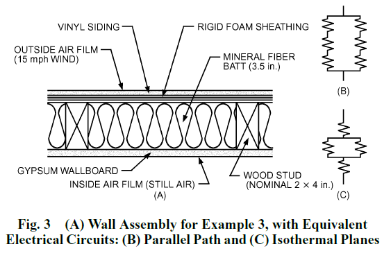
See this illustration taken from Chapter 27 of the HoF:
References:
My two cents if you have to use some complicated manual calculations such as for the zone method: you end up being faster and more accurate using THERM once you get the gist of it, and that includes how to draw properly in THERM and how to set your boundary conditions properly and on Heat Transfer)which surface to define the R-value calculation. There's a learning curve, but there's also pretty good documentation out there (thanks to standards such as Passivhaus who have got people interested in calculating bridges properly, and it's a worthy investment IMHO.
1Note that it actually reduces to half a panel and half an I-beam due to symmetry, but it's harder to grasp / visualize if you use THERM or another heat transfer software.


