Let's say there are three chillers as follows.
- Chiller no.1: 500RT
- Chiller no.2: 1000RT
- Chiller no.3: 1000RT
- Chiller Sqeuence: Chiller no.1, Chiller mo.2, Chiller no.3
- Minimum Part Load Ratio for all chillers: 0.1
- Maximum Part Load Ratio for all chillers: 1.0
- Minimum Unloading Ratio for all chillers: 0.25
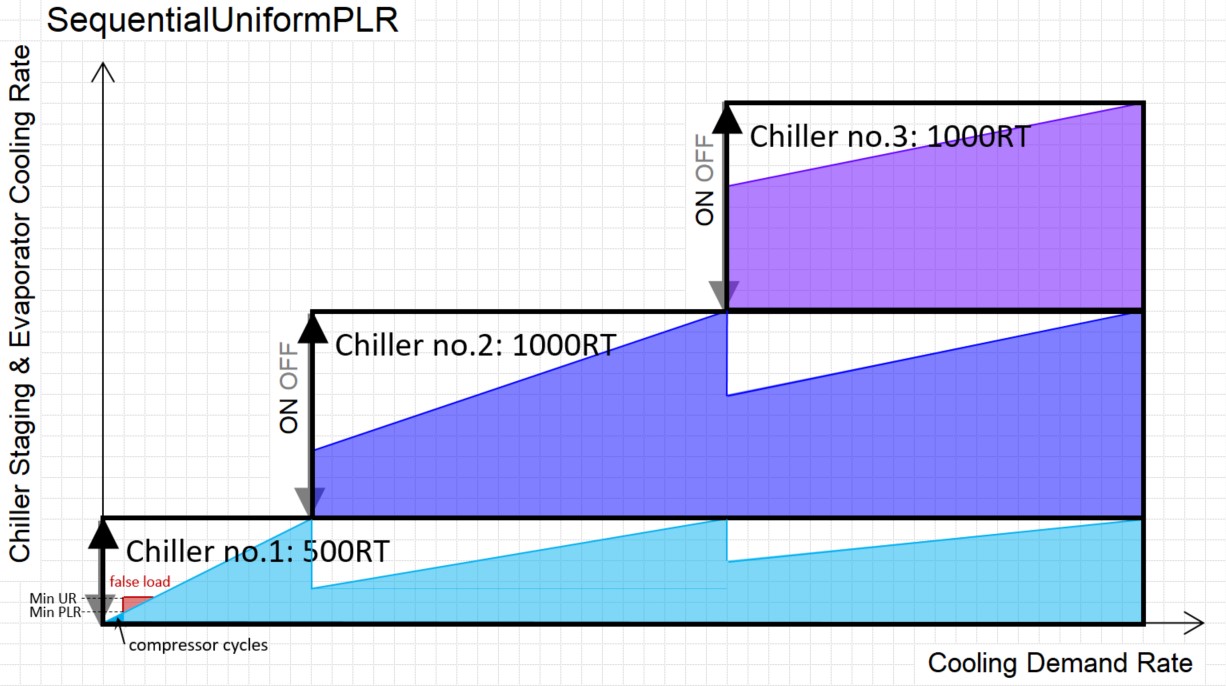
- Load Distribution Scheme: SequentialUniformPLR
Below is the chiller staging and chiller load distribution.
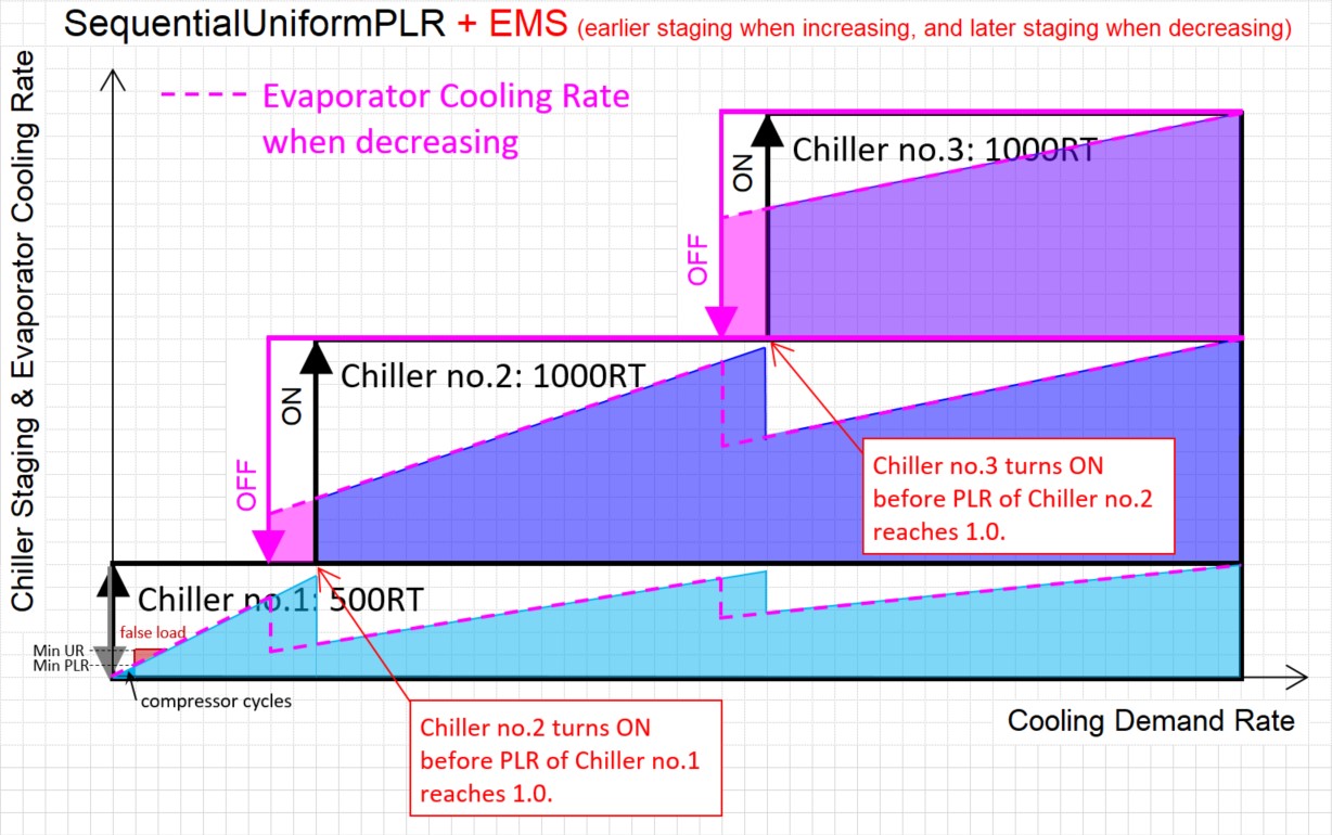
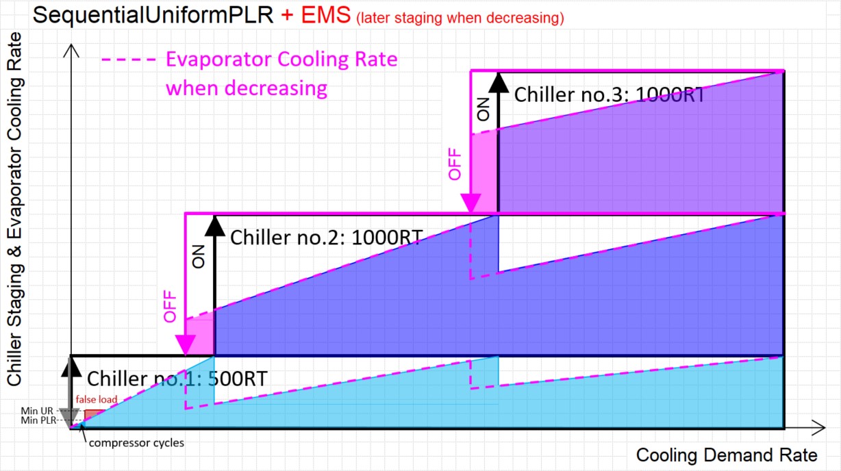
I think the timing that chiller no.2 turns OFF when the cooling demand is decreasing is the same as the timing that chiller no.2 turns ON when the cooling demand is increasing in EnergyPlus. However, they are not the same in real buildings to prevent frequent chiller switching as shown below.
How can I model this load distribution scheme? Has anyone modelled this with EMS? What Sensor/Actuator should be used and what kind of program should I write?
Moreover, in equipment that takes time to start, such as absorption chillers, Chiller no.2 starts before the PLR of Chiller no.1 reaches 1.0. How can I model this load distribution scheme? Any advice would be appreciated.