
I using Energyplus to simulate two equal capacity chillers autosized to meet the cooling load for an office. I already read this question and I checked my IDF based on it: 1- I sized my chillers using autosize and size factor of 0.5
Chiller:Electric:ReformulatedEIR,
CoolSys1 Chiller1,       !- Name
autosize,                !- Reference Capacity {W}
6.28,                    !- Reference COP {W/W}
6.6700,                  !- Reference Leaving Chilled Water Temperature {C}
34.4444,                 !- Reference Leaving Condenser Water Temperature {C}
autosize,                !- Reference Chilled Water Flow Rate {m3/s}
autosize,                !- Reference Condenser Water Flow Rate {m3/s}
WC_CENT_2010_PB_CAPFT,   !- Cooling Capacity Function of Temperature Curve Name
WC_CENT_2010_PB_EIRFT,   !- Electric Input to Cooling Output Ratio Function of Temperature Curve Name
LeavingCondenserWaterTemperature,  !- Electric Input to Cooling Output Ratio Function of Part Load Ratio Curve Type
WC_CENT_300to600_2010_PB_EIRFPLR,  !- Electric Input to Cooling Output Ratio Function of Part Load Ratio Curve Name
0.1000,                  !- Minimum Part Load Ratio
1.0000,                  !- Maximum Part Load Ratio
1.0000,                  !- Optimum Part Load Ratio
0.1000,                  !- Minimum Unloading Ratio
CoolSys1 Pump-CoolSys1 Chiller1Node,  !- Chilled Water Inlet Node Name
CoolSys1 Supply Equipment Outlet Node 1,  !- Chilled Water Outlet Node Name
CoolSys1 Chiller1 Water Inlet Node,  !- Condenser Inlet Node Name
CoolSys1 Chiller1 Water Outlet Node,  !- Condenser Outlet Node Name
,                        !- Fraction of Compressor Electric Consumption Rejected by Condenser
5.0000,                  !- Leaving Chilled Water Lower Temperature Limit {C}
ConstantFlow,            !- Chiller Flow Mode Type
0.0000,                  !- Design Heat Recovery Water Flow Rate {m3/s}
,                        !- Heat Recovery Inlet Node Name
,                        !- Heat Recovery Outlet Node Name
0.5;                     !- Sizing Factor
2- I used the operation scheme objects to specify the priority of using chillers.
PlantEquipmentOperationSchemes,
CoolSys1 Loop Operation Scheme List,  !- Name
PlantEquipmentOperation:CoolingLoad,  !- Control Scheme 1 Object Type
CoolSys1 Operation Scheme,  !- Control Scheme 1 Name
PlantOnSched;            !- Control Scheme 1 Schedule Name

PlantEquipmentOperation:CoolingLoad,
CoolSys1 Operation Scheme,  !- Name
0,                 !- Load Range 2 Lower Limit {W}
100000000000000,         !- Load Range 2 Upper Limit {W}
CoolSys1 Equipment List 2;  !- Range 2 Equipment List Name

PlantEquipmentList,
CoolSys1 Equipment List 2,  !- Name
Chiller:Electric:ReformulatedEIR,  !- Equipment 1 Object Type
CoolSys1 Chiller1,       !- Equipment 1 Name
Chiller:Electric:ReformulatedEIR,  !- Equipment 2 Object Type
CoolSys1 Chiller2;       !- Equipment 2 Name
3- I used the load distribution scheme in the plant loop definition:
PlantLoop,
CoolSys1_Demand,         !- Name
Water,                   !- Fluid Type
,                        !- User Defined Fluid Type
CoolSys1 Sec Loop Operation,  !- Plant Equipment Operation Scheme Name
CoolSys1 Demand Inlet Node,  !- Loop Temperature Setpoint Node Name
98,                      !- Maximum Loop Temperature {C}
1,                       !- Minimum Loop Temperature {C}
autosize,                !- Maximum Loop Flow Rate {m3/s}
0,                       !- Minimum Loop Flow Rate {m3/s}
autocalculate,           !- Plant Loop Volume {m3}
CoolSys1 Demand Supply Side Inlet Pipe Inlet Node,  !- Plant Side Inlet Node Name
CoolSys1 Demand Supply Side Outlet Pipe Outlet Node,  !- Plant Side Outlet Node Name
CoolSys1 Demand Supply Side Branches,  !- Plant Side Branch List Name
CoolSys1 Demand Supply Side Connectors,  !- Plant Side Connector List Name
CoolSys1 Demand Inlet Node,  !- Demand Side Inlet Node Name
CoolSys1 Demand Outlet Node,  !- Demand Side Outlet Node Name
CoolSys1 Demand Demand Side Branches,  !- Demand Side Branch List Name
CoolSys1 Demand Demand Side Connectors,  !- Demand Side Connector List Name
SequentialLoad;             !- Load Distribution Scheme
When I run the simulation for a day I receive weird load distribution as follow:
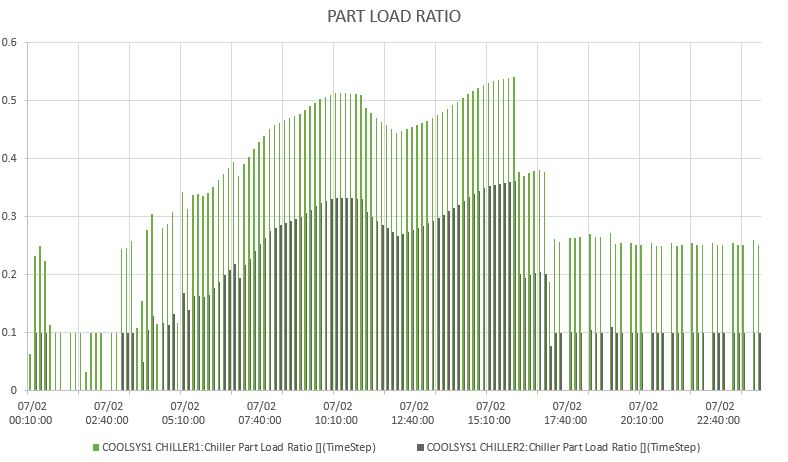 As can be seen, the first chiller doesn't reach its maximum PLR!!
I tried many modifications but no matter what, the load distribution doesn't work properly. Here is my idf file.
As can be seen, the first chiller doesn't reach its maximum PLR!!
I tried many modifications but no matter what, the load distribution doesn't work properly. Here is my idf file.


