I was modeling a tankless coil system with a source side plant loop connected with boiler loop through a heat exchanger. Following chart shows the plant loop I've set up in EnergyPlus.
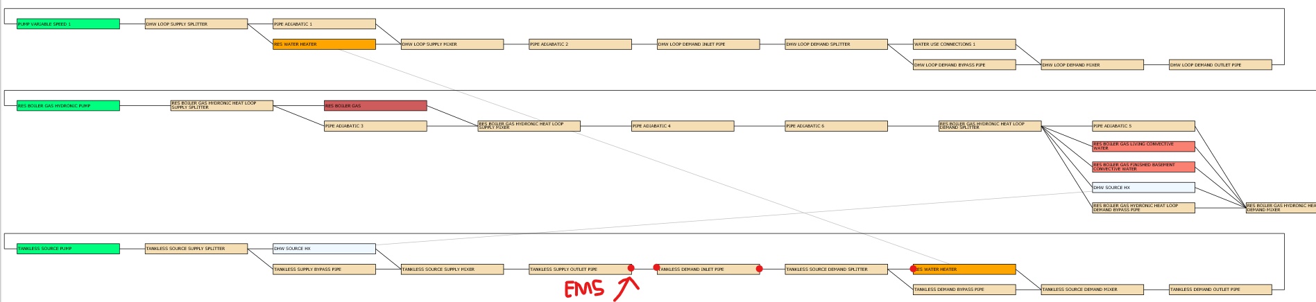
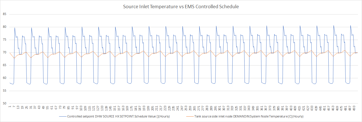
My purpose is to control the tank source side inlet temperature using EMS, which basically follows the useful answer by @Neal Kruis in this question: Heating demand not passed from DHW loop to Boiler loop Problem occurred when I checked the output variables. I output the node temperatures of those red points in the chart. And the node under EMS controls is also marked. This node is supposed to be identical to the tank source side inlet node since all the pipes are adiabatic, so that I could achieve the control of tank source side to ensure tankless coil is delivering enough heat. But the simulation results show that the last three nodes (in the demand side of loop) are of the same temperature different from the controlled supply outlet node temperature. The differences are plotted below:

I have no idea how it happened that these connected neighbor nodes are of different temperatures. Although I changed the EMS controlled point to the tank inlet node, it still didn't work, the inlet temperature kept as these unknown values, it seems there's somewhere else in E+ simulation that has override the values I want to deliver. Do you guys have any idea how to control these node temperatures? Or do you guys have any idea how to model this tankless system with good control?
Description of model:
Tank:
Waterheater:Mixedwith volume 0.00379 m3 andModulatecontrol type (tankless setting), source side connected with a loop in demand branch, source side control mode isIndirectHeatAlternateSetpoint(which I activated in PR#7286 branch) the setpoint of alternate schedule is 70C which does nothing but keeping the source side always on (it's critical for tankless system because of its small volume. It will fall much lower than setpoint over the hours when source side turned off)EMS:
EnergyManagementSystem:Program,
res_dhw_program,         !- Name
Set CpWater = (@CpHW TankTemp),  !- Program Line 1
If (SourceMassFlowRate>0),  !- Program Line 2
Set hx_temp_setpoint = whSetpoint+((-UseHeat-LossHeat-OffCycleHeat-OnCycleHeat)/(SourceMassFlowRate*CpWater)),  !- A4
Else,                    !- A5
Set hx_temp_setpoint = 60,  !- A6
EndIf;                   !- A7