

On my most recent energy simulation project, I had to model multiple water cooled DX fan coil units with hydronic heating coils, each serving a unique zone in a production facility. These zones had both high internal lighting and latent loads. OpenStudio and EnergyPlus were used to not only determine the baseline energy consumption, but also to assess the ability of the HVAC system as designed to control zone temperature and humidity.
The manufacturer of these fan coil units termed them to be heat pumps, but this is a misnomer. Each fan coil unit was configured with a DX cooling coil with its own refrigerant compressor along with a hydronic heating coil. The compressor does not provide reverse circuiting as in a true heat pump, hence the DX coil only provides cooling. Heating is accomplished by a hydronic heating coil within the fan coil unit.
These DX fan coil units are similar to distributed heat pumps in that the heat from the refrigerant condensing process is rejected into a common 2 pipe building hydronic loop. In order to effectively reject heat to the hydronic loop, the loop temperature is nominally set at 110°F [43.3°C]. In conditions where most of the DX cooling compressors are operating the loop temperature will continue to rise and when it exceeds a nominal temperature of about 120°F [48.9°C].fluid coolers reject the excess heat to the ambient outside air conditions. In conditions where most of the DX cooling compressors are not operating and there is a call for heating by the space thermostats, the loop temperature will fall below the nominal setpoint of 110°F [43.3°C]. In this case, a heating boiler is used to maintain the building loop set-point temperature.
The DX fan coil units are nominally configured to provide either cooling or heating, but not both simultaneously, hence they are normally set up to operate on space temperature. However, they could also operate the DX coil to provide space humidity control with the hydronic coil providing reheat. The ratio of cooling coil capacity to heating coil capacity is about 1.0 for these units.
The EnergyPlus HVACTemplate:Zone:PTHP could be considered for modelling these units by setting the Heat Pump Heating Coil Availability Schedule to Off and by defining the Supplemental Heating Coil Type to Hydronic. However, the availability of the Supplemental Heating Coil is overridden by the Maximum Outdoor Dry-Bulb which is limited to 21°C [69.8°F]. On this particular project, the primary strategy was for space humidity control. Hence, this limitation is unacceptable for space humidity control when reheat is required.
The Coil:Cooling:DX:SingleSpeed object only allows for the Condenser Type to be either AirCooled or EvaporativelyCooled. Water cooled is not an available option.
As there was no way to model these units directly in OpenStudio 2.5.0 or EnergyPlus 8.9, and given the time constraints available on the project, I had to use the following work around:
These DX fan coil units were developed in the OpenStudio GUI for the EnergyPlus text input file in three interrelated components. Firstly, the DX draw-through fan coil units with hydronic heating coil as shown in the following circuit diagram, with the DX cooling coil to the left of the hydronic heating coil at the top of the circuit.
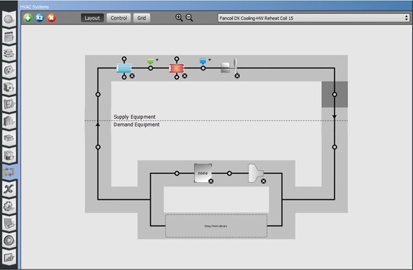
Figure 1 Typical DX Fan Coil Unit Air Loop Serving a Thermal Zone 15
AirLoopHVAC,
     Fancoil DX Cooling-HW Reheat Coil 15,  !- Name
     ...
Next, the DX cooling coil connected to the reciprocating water-cooled compressor where the pump is a representation of the movement of Freon. The pump head was set to 0 so that the hydronic circuit could simulate a Freon circuit. The DX compressor was modeled as a Water Cooled Reciprocating Chiller. In this case, the cooling coil is at the bottom of the circuit and the compressor is at the top of the circuit.
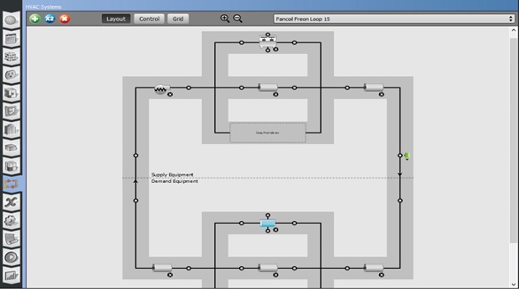
Figure 2 DX Cooling Coil and Compressor Freon Circuit Loop 15
PlantLoop,
    Fancoil Freon Loop 15,   !- Name
    Water,                   !- Fluid Type
    ,                        !- User Defined Fluid Type
    Fancoil Freon Loop 15 Operation Schemes,  !- Plant Equipment Operation Scheme Name
    ...

Pump:VariableSpeed,
    Var Spd Pump 15,         !- Name
    ...
    0,                       !- Design Pump Head {Pa}
    ...

Chiller:Electric:EIR,
    WaterCooled Reciprocating Chiller 15,  !- Name
    Autosize,                !- Reference Capacity {W}
    4.2019115890084,         !- Reference COP {W/W}
    6.67,                    !- Reference Leaving Chilled Water Temperature {C}
    43.33,                   !- Reference Entering Condenser Fluid Temperature {C}
    ...
    WaterCooled,             !- Condenser Type
    ...
    NotModulated,            !- Chiller Flow Mode
    ...
Finally, the reciprocating water-cooled compressor interconnected to the building condenser loop. This is shown as the upper most component below the dashed horizontal line in Figure 3. The hydronic heating coil within the DX fan coil unit is shown below the water-cooled compressor. This figure also shows the condenser loop pump in the upper left portion of the circuit and the boiler in the upper most portion of the circuit to the left of the fluid cooler.
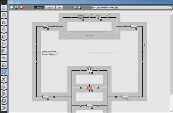
Figure 3 Building Condenser Loop Circuit
FluidCooler:SingleSpeed,
    Single Speed Fluid Cooler 1,  !- Name
    ...
    58.93,                   !- Design Entering Water Temperature {C}
    ...

Boiler:HotWater,
    HW Boiler 1,             !- Name
    ...
    43.33,                   !- Design Water Outlet Temperature {C}
    ...

Pump:VariableSpeed,
    Condenser Loop Pump,     !- Name
    ...
    179352,                  !- Design Pump Head {Pa}
    ...
This work around solution foregoes the unique characteristics of a DX cooling coil and instead substitutes the characteristics of a chilled water coil.
In conclusion, when a project has to be delivered within a schedule, some compromises have to be made in the building energy model. These compromises require thoughtful reflection on their impact on the model. Zone temperature and space humidity control was primary concern, rather than a precise energy analysis.
The ability to model a DX cooling coil with a water cooled compressor option within EnergyPlus would offer the flexibility to model air loops with a common building 2-pipe condenser loop.
Can a water cooled DX system be considered in future releases of OpenStudio and EnergyPlus?
Footnote:
I have had a very recent enquiry regarding a multi-residential building proposing to use the same type of DX cooling fan coils with hydronic heating coils.
