I have found this problem in EnergyPlus for quite a while already perhaps from v8.5.
I have set the load distribution scheme to "Sequential Load" as below.
PlantLoop,
ChilledWaterLoop Chilled Water Loop,  !- Name
Water,                   !- Fluid Type
,                        !- User Defined Fluid Type
ChilledWaterLoop Chiller Operation,  !- Plant Equipment Operation Scheme Name
ChilledWaterLoop ChW Supply Outlet,  !- Loop Temperature Setpoint Node Name
98,                      !- Maximum Loop Temperature {C}
1,                       !- Minimum Loop Temperature {C}
autosize,                !- Maximum Loop Flow Rate {m3/s}
0,                       !- Minimum Loop Flow Rate {m3/s}
autosize,                !- Plant Loop Volume {m3}
ChilledWaterLoop ChW Supply Inlet,  !- Plant Side Inlet Node Name
ChilledWaterLoop ChW Supply Outlet,  !- Plant Side Outlet Node Name
ChilledWaterLoop ChW Supply Side Branches,  !- Plant Side Branch List Name
ChilledWaterLoop ChW Supply Side Connectors,  !- Plant Side Connector List Name
ChilledWaterLoop ChW Demand Inlet,  !- Demand Side Inlet Node Name
ChilledWaterLoop ChW Demand Outlet,  !- Demand Side Outlet Node Name
ChilledWaterLoop ChW Demand Side Branches,  !- Demand Side Branch List Name
ChilledWaterLoop ChW Demand Side Connectors,  !- Demand Side Connector List Name
SequentialLoad,          !- Load Distribution Scheme
,                        !- Availability Manager List Name
SingleSetpoint,          !- Plant Loop Demand Calculation Scheme
CommonPipe;              !- Common Pipe Simulation

PlantEquipmentList,
ChilledWaterLoop 3 Chillers,  !- Name
Chiller:Electric:EIR,    !- Equipment 1 Object Type
WCC-101,                 !- Equipment 1 Name
Chiller:Electric:EIR,    !- Equipment 2 Object Type
WCC-102,                 !- Equipment 2 Name
Chiller:Electric:EIR,    !- Equipment 3 Object Type
WCC-103;                 !- Equipment 3 Name
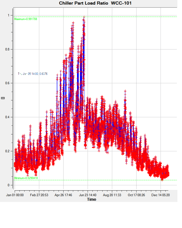
At the beginning of the simulation run, the load distributed to WCC-101 (1st Chiller) seemed behaving normally with a gradual increase up to 0.99.
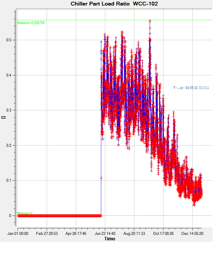
Once the cooling load exceeded the capacity of my 1st chiller, WCC-102 (2nd chiller) kicked in. Afterwards, both chillers operates continuously as uniform load distribution until the end of simulation run. The 2nd chiller would not stop operating even with the cooling demand can be handled by the 1st chiller.
Has any one experienced this and has an explanation to it?