
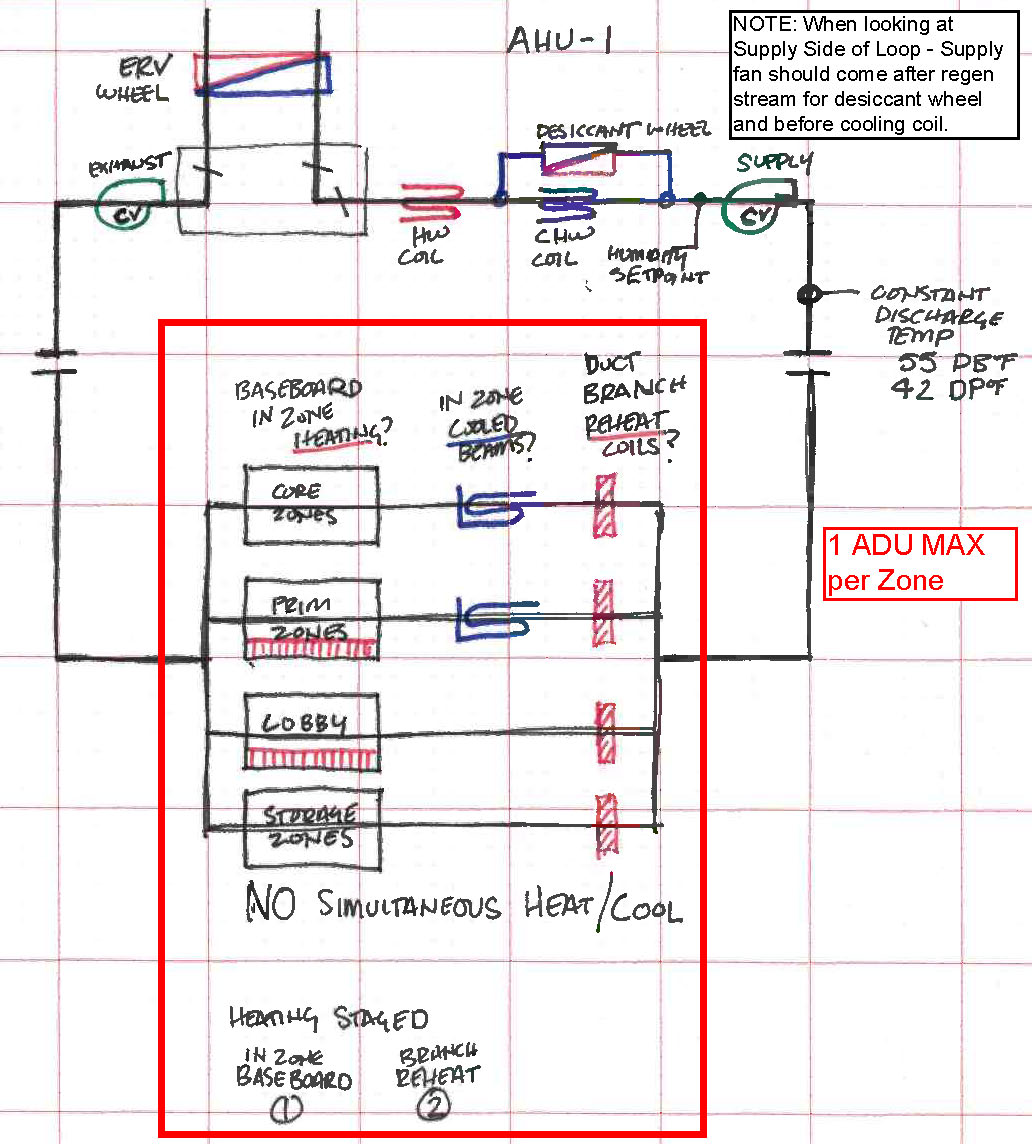
I am nearly convinced that simply modeling the system (diagram below) with in-zone equipment for reheat will be easiest, but I would like to see if anyone has feedback on alternative methods for modeling branch in-duct HW heating coils upstream of chilled-beams. Some zones also have perimeter HW radiant heating.
There is no simultaneous heating and cooling amongst the various downstream heating equipment and the chilled-beams.
Original Diagram (there is an inconsistency with the upstream supply fan location, but that is not at question.) C:\fakepath\AHU-1 Diagram.jpg
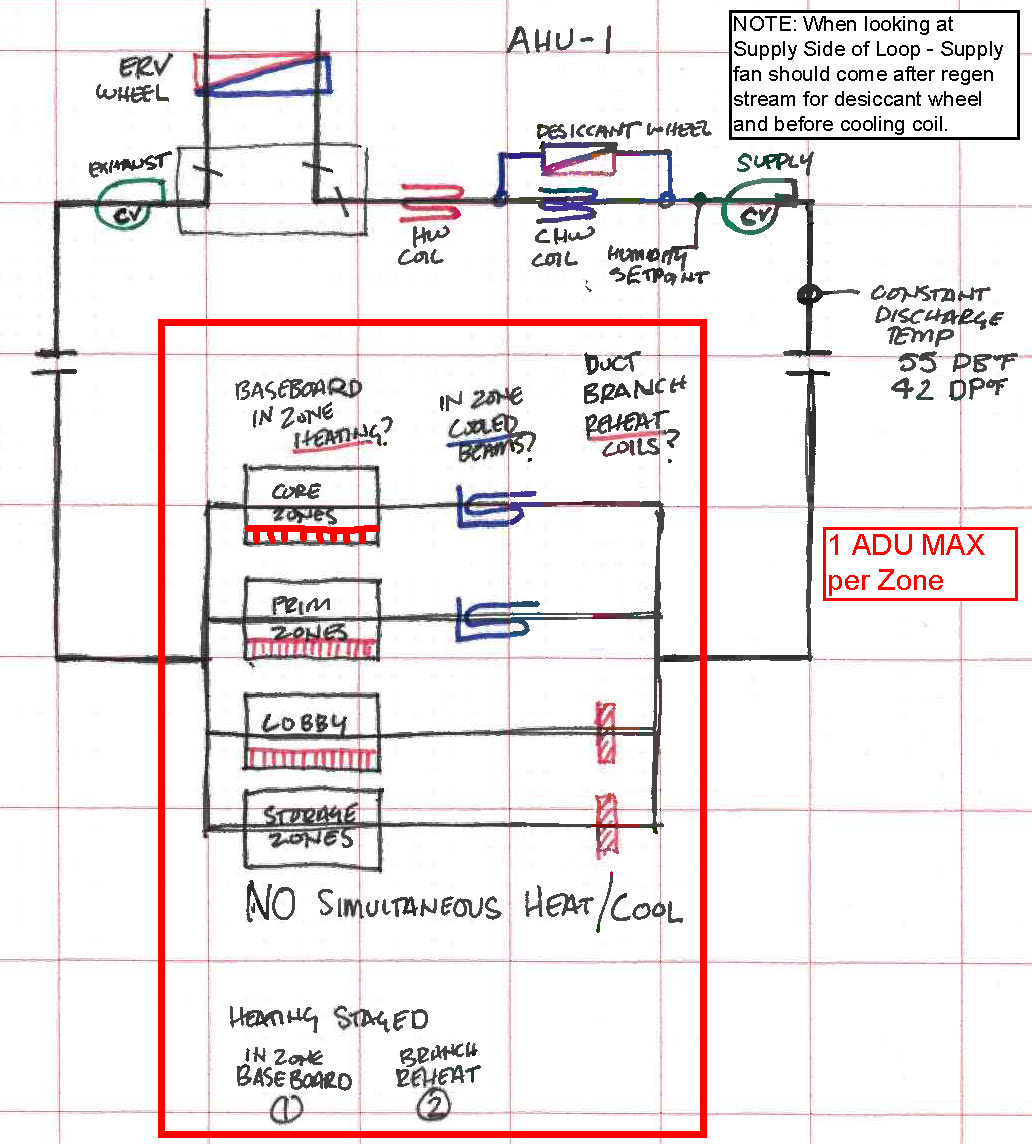
Alternative (Simple) method - radiant in-zone reheating equipment. C:\fakepath\AHU-1 Diagram - Simple.jpg


