Question-and-Answer Resource for the Building Energy Modeling Community
Get started with the Help page
Ask Your Question
2

The vertex sizes are 7 for the base surface and 14 for the outside boundary surface. Please check inputs.

asked 2023-06-20 15:11:46 -0500

Sneog's avatar

updated 2023-08-26 07:25:11 -0500

An error occurs when I try to simulate my file, and I receive the following result:

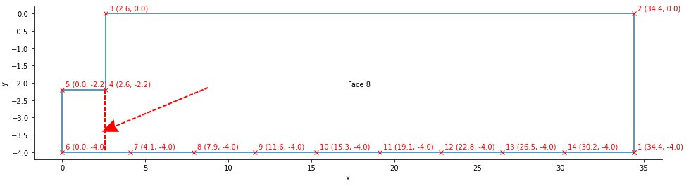
** Severe ** RoofCeiling:Detailed="FACE 8", Vertex size mismatch between base surface: FACE 8 and outside boundary surface: FACE 348
** ~~~ ** The vertex sizes are 14 for the base surface and 7 for the outside boundary surface. Please check inputs.
** Severe ** RoofCeiling:Detailed="FACE 348", Vertex size mismatch between base surface: FACE 348 and outside boundary surface: FACE 8
** ~~~ ** The vertex sizes are 7 for the base surface and 14 for the outside boundary surface. Please check inputs.
** Fatal ** GetSurfaceData: Errors discovered, program terminates.

Upon inspecting the 3D view, I noticed that Surface 8 is labeled as a Roof Ceiling, even though it should be the ceiling of the first floor in a two-story building.

My questions are: How can I change the surface setting using FloorspaceJS, and is this the actual cause of the severe error, or is there another problem causing it?

edit retag flag offensive close merge delete

Comments

Hello! I can give this one a shot. The fact that 14 is double 7, makes me think a surface might be doubled somewhere. Would you be able to add your .osm file here?

IanVG's avatar IanVG  ( 2023-06-21 17:11:27 -0500 )edit

Thank you for your help. I can't upload a .osm File here. I hope you can access it with the following link to the file via dropbox.

link text

Sneog's avatar Sneog  ( 2023-06-22 04:59:51 -0500 )edit

Hey Sneog, so I opened up your file in Sketchup using the SketchUp OpenStudio plugin (version 1.6.0). I am using the OpenStudioApplication version 3.6.1. Your file reports that it was saved using OpenStudio 3.5. This may be a bug during the update to the newer OpenStudio version, but the OpenStudio spaces are not created correctly. All I am seeing are skeleton lines (no surfaces in the spaces). It also looks like there is a Guide Point located at 0,0,0 for each space which looks wonky, but I couldn't say why.

IanVG's avatar IanVG  ( 2023-07-08 13:30:35 -0500 )edit
1

Okay, again, I don't know if this is a solution or not, but I used this tool to add placeholder CAD objects to the GBxml (exported a GBXml from the .osm you provided). When I ran the imported GBxml in a new .osm file, I didn't get the errors associated with the vertex surfaces, I did however get errors with the construction, which I assume could be fixed by fixing the construction types.

IanVG's avatar IanVG  ( 2023-07-08 14:05:49 -0500 )edit

2 Answers

Sort by ยป oldest newest most voted
4

answered 2023-07-10 03:07:13 -0500

I've filled an issue at NREL/EnergyPlus#10103 to address this corner case. The floor and ceiling are perfectly matching with 14 vertices, but the issue that you have a non-convex surface here, and EnergyPlus will stop trying to remove colinear vertices as soon a surface is deemed non-convex. Your floor is processed as being 7 vertices but the roof stays at 14 vertices because it finds a non-convex situation before it even gets to the colinear vertices, and it fails.

This is the floor:

image

And logically, the reversed ceiling:

image

I've included more information on the issue itself if you are curious.

The fix is to break both your floor and ceiling surfaces into two rectangular surfaces.. (Ideally you also do not want to make non-convex zones...)

image description

edit flag offensive delete link more

Comments

Very cool! Thanks for the great insight. I should have checked the extra diagnostics option before running this. Could you expound/link to on why zones should also not be non-convex? I assumed that maintaining convex surfaces was good practice, but I wasn't aware of this rule applying to zones (and I assume spaces) as well.

IanVG's avatar IanVG  ( 2023-07-10 22:37:14 -0500 )edit

Okay, found the answer to my own question via this youtube video. On page 49 of the EnergyPlus Input Output Reference Manual, you find that convex spaces/zones are necessary for doing interior solar radiative heating calculations. So for your example, I would break up your zone into two zones (they'll both be rectangular prisms). And set the 'wall' separating the spaces/zones to be an airwall.

IanVG's avatar IanVG  ( 2023-07-10 22:50:41 -0500 )edit
2

answered 2023-07-08 14:17:42 -0500

IanVG's avatar

This is not a direct answer to your question, but refer to this response for an explanation of how to fix vertex mismatch errors. Basically one surface has the correct number of vertices and the other doesn't. Splitting the surface into multiple surfaces and running the surface match program may help fix this.

Second this is that any roof OR ceiling can/will be labeled as RoofCeiling. Face 8 has 14 vertices while the matching Face 348 has only 7 vertices. One of these surfaces is modeled wrong.

And to answer your other question: I am not sure how you would fix this is FloorSpaceJS. I have preferred to use SketchUp for modeling the building geometry because of the flexibility SketchUp provides in diagnosing and fixing these kinds of errors. FloorSpaceJS has limited use for more multi-storey geometry creation (in my opinion). The Spider gbXML fixer tool may be your best bet for fixing this geometry.

edit flag offensive delete link more

Your Answer

Please start posting anonymously - your entry will be published after you log in or create a new account.

Add Answer

Training Workshops

Careers

Question Tools

1 follower

Stats

Asked: 2023-06-20 15:11:46 -0500

Seen: 162 times

Last updated: Aug 26 '23