Question-and-Answer Resource for the Building Energy Modeling Community
Get started with the Help page
Ask Your Question
3

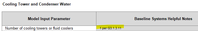
Number of Cooling Towers for ASHRAE90.1 Baseline

asked 2023-05-09 00:34:26 -0500

Keigo's avatar

updated 2023-05-10 20:30:36 -0500

As per the title. Sorry for asking about a very fundamental requirement of ASHRAE90.1 Appendix G, but I'm not 100% sure. What is the number of cooling towers for the Baseline case?

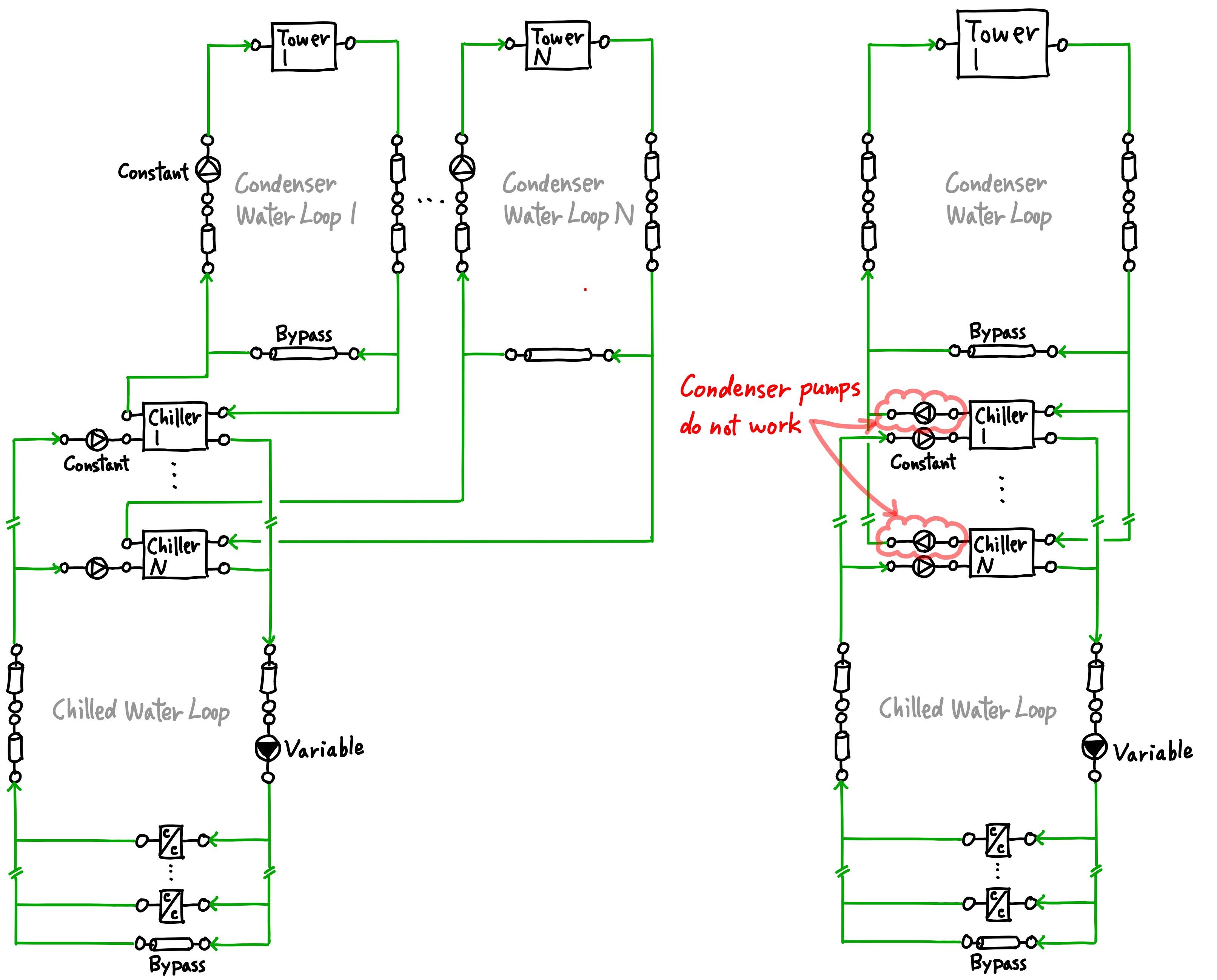
I have been modeling Tower per Chiller as shown on the left side of the schematic below. If the Baseline case has 10 chillers, it also has 10 cooling towers.

Supporting document: [ANSI/ASHRAE/IES Standard 90.1 Performance Rating Method Reference Manual] (https://www.pnnl.gov/main/publication...)

image description


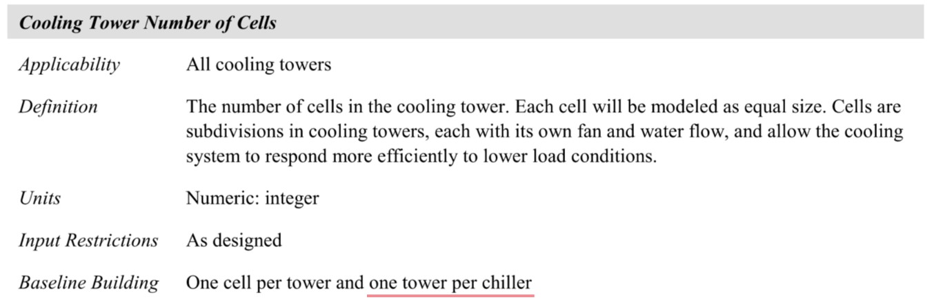
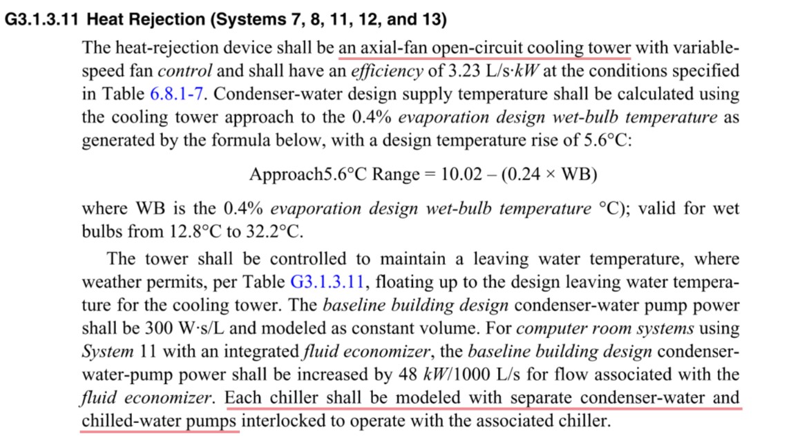
On the other hand, the original requirement of G3.1.3.11 states that the heat-rejection device shall be an axial-fan open-circuit cooling tower. It also states that each chiller shall be modeled with separate condenser-water pumps. If I interpret these requiremrnts as they are, the schematic would look like the one on the right below.

image description

image description

Which is correct, Tower per Chiller or only one big Tower?

The propbem of the only one big Tower is that the condenser loop shown on the right does not work in EnergyPlus. It seems that EnergyPlus does not allow to model condenser pumps immediately before or after chillers. When I modelled the schematic on the right in EnergyPlus, no warning/severe error about component connection appeared, but there was no water flow on the condenser loop. Condenser pumps and one cooling tower did not work.


SUPPLEMENT

EngineeringReference describes pump placement relus in EnergyPlus.

image description

edit retag flag offensive close merge delete

Comments

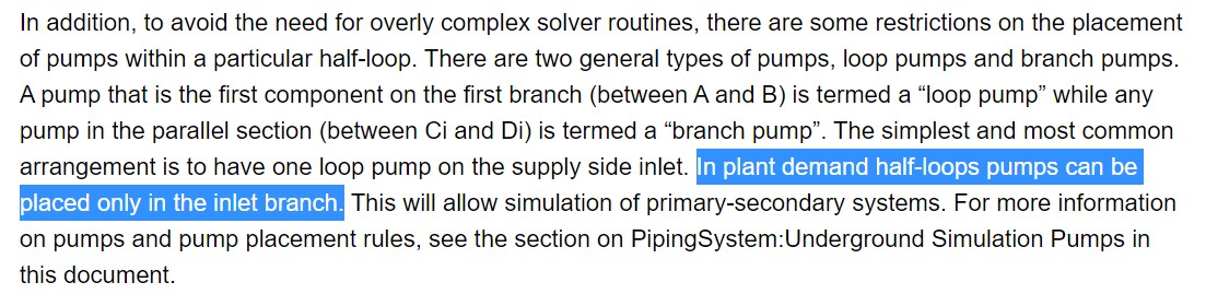
Based on that description and the diagram in the reference manual I would think you should be able to have a "primary" pump attached to the condenser side of the chiller and a separate branch "secondary" pump serving tower branch loop. Maybe it's a bug?

ashopinion's avatar ashopinion  ( 2023-05-11 11:28:54 -0500 )edit

I'm not sure if I understand your comment correctly. Are the "primary" pumps already shown in my sketch highlighted with the red clouds? Is the "secondary" pump added in the supply inlet branch of the condenser water loop? If that's the case, the primary pumps do not work, and I don't think the secondary pump complies with the pump configuration described in G3.1.3.11.

Keigo's avatar Keigo  ( 2023-05-11 11:55:44 -0500 )edit

Your highlighted pumps in red would be the condenser loop primary pumps and you should be able to add a secondary pump to that tower loop. To your original question, it's not clear to me if you have to do it that way or why it doesn't seem to work in the way you've configured it. I would try the following workaround; create a secondary loop pump for the tower and assign all the appendix G pump power allowance.

ashopinion's avatar ashopinion  ( 2023-05-11 12:05:59 -0500 )edit

EnergyPlus cannot model what you suggest because

   ** Severe  ** Input Error: Pumps on both loop sides must utilize a common pipe

but CondenserLoop does not have common pipe input field.

Moreover, if one big Tower is correct, the point is not finding workaround or makeshift to run the simulation. EnergyPlus is one of the authorized energy simulation programs. It must be capable of modelling ASHRAE90.1 Baseline case accurately.

Keigo's avatar Keigo  ( 2023-05-11 19:44:13 -0500 )edit
Keigo's avatar Keigo  ( 2023-05-13 04:33:20 -0500 )edit

2 Answers

Sort by ยป oldest newest most voted
2

answered 2023-05-17 10:58:48 -0500

The language is indeed confusing. I checked with ASHRAE members who work on Appendix G. The short answer is that the correct interpretation is one cooling tower with one cell per chiller. The longer answer is that having one tower/one cell to serve multiple chillers would probably not work as the nozzles of an open cooling tower would not be able to operate at the reduced flow rates under those conditions.

edit flag offensive delete link more

Comments

Let me confirm just in case. Does that mean my water-side schematic sketch on the left is correct?

Keigo's avatar Keigo  ( 2023-05-17 11:07:58 -0500 )edit

Add that to the list of things the standard committee needs to clarify in 90.1-2025...

ashopinion's avatar ashopinion  ( 2023-06-07 12:32:35 -0500 )edit

@ashopinion, I think that anyone can propose a clarification: https://www.ashrae.org/technical-reso...

Jeremy's avatar Jeremy  ( 2023-06-07 12:45:08 -0500 )edit
0

answered 2023-05-09 11:45:06 -0500

ashopinion's avatar

PNNL would say one tower per chiller. GBCI (i.e. LEED projects) would say one tower for the entire plant. See screenshot from the LEED MEPC. Appendix G refers to the heat rejection device (singular tense). image description

edit flag offensive delete link more

Comments

I know the LEED Minimum Energy Performance Calculator. What's your opinion? How do you normally model the condenser loop?

If the LEED MEPC is correct and we should model only one big Tower, EnergyPlus cannot be used to model it.

Keigo's avatar Keigo  ( 2023-05-09 11:59:46 -0500 )edit

I've only modeled system 7 in eQUEST and am not familiar with that apparent limitation. Would love others to chime in as well.

ashopinion's avatar ashopinion  ( 2023-05-09 13:05:54 -0500 )edit

Sytem 7 has cooling tower(s). Which did you model in eQUEST, Tower per Chiller or only one big Tower?

Keigo's avatar Keigo  ( 2023-05-09 18:55:28 -0500 )edit

I may be wrong but our current interpretation of Appendix G is in line with GBCI so we only model one tower, irrespective of the number of chillers in play.

ashopinion's avatar ashopinion  ( 2023-05-10 13:23:22 -0500 )edit

I see. Thank you for your opinion.

Keigo's avatar Keigo  ( 2023-05-10 19:34:27 -0500 )edit

Your Answer

Please start posting anonymously - your entry will be published after you log in or create a new account.

Add Answer

Careers

Question Tools

1 follower

Stats

Asked: 2023-05-09 00:34:26 -0500

Seen: 305 times

Last updated: May 23 '23