Air-Chiller temperature setpoint


How do I set a setpoint for an Air-Chiller to start cooling when the internal temperature is -18°C and stop when the internal temperature reaches -22°C.
add a comment
First time here? Check out the Help page!
How do I set a setpoint for an Air-Chiller to start cooling when the internal temperature is -18°C and stop when the internal temperature reaches -22°C.
If you review the EnergyPlus example file named RefrigeratedWarehouse.idf, it should contain all of the object types that you will need. Below is an example of one air chiller and the thermostat settings for the refrigeration zone served by that chiller in that example file.
!-   ===========  ALL OBJECTS IN CLASS: Refrigeration:AirChiller ===========
! Subfreezer
! -25C is desired zone temperature
! max sensible load was 136,000W with ideal air (no latent included)
! avg cap was 77,000W with ideal air (no latent included)
! Try with 300,000W total and DT1 of 8C, so unit load factor is 40,000 W/DeltaC
! See BAC AS5S-4084-050L, fan 0.5 HP (0.5 hp = 373 W), airflow 26,250 cfm(1 ft3 = 0.02833 m3, so ~12.4 m3/s),
!                     frosted capacity 20,650 B/h-F (~10,900 W/C), so need 3 of them
!  Will do Evap T of -33C, let heater = 200W,
!  Use electric defrost - capacity large to limit time and handle latent load
!  Electric defrost capacity, BAC recommends 11 W/ft2 (this model has 5,006 ft2), so 55066W

Refrigeration:AirChiller,
  SubFreezerAirChiller_1,  !- Name
  AvailAllYear,            !- Availability Schedule Name
  UnitLoadFactorSensibleOnly,  !- Capacity Rating Type
  10900.,                  !- Rated Unit Load Factor {W/K}
  ,                        !- Rated Capacity {W}
  ,                        !- Rated Relative Humidity {percent}
  -33.,                    !- Rated Cooling Source Temperature {C}
  8.,                      !- Rated Temperature Difference DT1 {deltaC}
  11.,                     !- Maximum Temperature Difference Between Inlet Air and Evaporating Temperature {deltaC}
  ,                        !- Coil Material Correction Factor {dimensionless}
  ,                        !- Refrigerant Correction Factor {dimensionless}
  LinearSHR60,             !- Capacity Correction Curve Type
  ,                        !- Capacity Correction Curve Name
  1.5,                     !- SHR60 Correction Factor {dimensionless}
  200.,                    !- Rated Total Heating Power {W}
  AirChillerDripDownSched1,!- Heating Power Schedule Name
  ,                        !- Fan Speed Control Type
  375.,                    !- Rated Fan Power {W}
  12.4,                    !- Rated Air Flow {m3/s}
  ,                        !- Minimum Fan Air Flow Ratio {dimensionless}
  Electric,                !- Defrost Type
  TimeSchedule,            !- Defrost Control Type
  AirChillerDefrostSched1, !- Defrost Schedule Name
  AirChillerDripDownSched1,!- Defrost Drip-Down Schedule Name
  55066.,                  !- Defrost Power {W}
  ,                        !- Temperature Termination Defrost Fraction to Ice {dimensionless}
  ,                        !- Vertical Location
  ;                        !- Average Refrigerant Charge Inventory {kg}
The air chiller will then be part of the case and walkin list, as well as the zone HVAC refrigeration chiller set.
Refrigeration:CaseAndWalkInList,
  SubFreezerAirChillerList,!- Name
  SubFreezerAirChiller_1,  !- Case or WalkIn 1 Name
  SubFreezerAirChiller_2,  !- Case or WalkIn 2 Name
  SubFreezerAirChiller_3;  !- Case or WalkIn 3 Name

ZoneHVAC:RefrigerationChillerSet,
  SubFreezerChillerSet,    !- Name
  ,                        !- Availability Schedule Name
  SubFreezer,              !- Zone Name
  ,                        !- Air Inlet Node Name
  ,                        !- Air Outlet Node Name
  SubFreezerAirChiller_1,  !- Air Chiller 1 Name
  SubFreezerAirChiller_2,  !- Air Chiller 2 Name
  SubFreezerAirChiller_3;  !- Air Chiller 3 Name
The zone HVAC refrigeration chiller set is then assigned to the zone HVAC equipment list.
ZoneHVAC:EquipmentList,
  SubFreezerEquipment,     !- Name
  SequentialLoad,          !- Load Distribution Scheme
  ZoneHVAC:RefrigerationChillerSet,  !- Zone Equipment 1 Object Type
  SubFreezerChillerSet,    !- Zone Equipment 1 Name
  1,                       !- Zone Equipment 1 Cooling Sequence
  1,                       !- Zone Equipment 1 Heating or No-Load Sequence
  ,                        !- Zone Equipment 1 Sequential Cooling Fraction Schedule Name
  ;                        !- Zone Equipment 1 Sequential Heating Fraction Schedule Name
This equipment list is referenced by the zone HVAC equipment connections, which also defines the zone that is connected to that equipment list.
ZoneHVAC:EquipmentConnections,
  SubFreezer,              !- Zone Name
  SubFreezerEquipment,     !- Zone Conditioning Equipment List Name
, !- Zone Air Inlet Node or NodeList Name ...Thank you @Boranian for you answer,
I used the example you mentioned above and adapted it to my problem, I also set the temperature difference between cutoff and setpoint to 4C as you said, but unfortunately this does not work and gives the following error
Severe - DualSetPointWithDeadBand: When Temperature Difference Between Cutout And Setpoint is applied, the heating setpoint is greater than the cooling setpoint. occurs in Zone=WALK-IN ZONE During Warmup, Environment=RUN PERIOD, at Simulation time=08/10 00:00-00:03 Zone Heating ThermostatSetPoint=-22 Zone Cooling ThermostatSetPoint=-22
@Zakaria I've just edited my post for extra details. Essentially, try lowering the heating thermostat setpoint while keeping the cutout temperature of 4C and run a new simulation.
Thank you @Boranian for you answer,
I used the example you mentioned above and adapted it to my problem, I also set the temperature difference between cutoff and setpoint to 4C as you said, but unfortunately this does not work and gives the following error.
* Severe * DualSetPointWithDeadBand: When Temperature Difference Between Cutout And Setpoint is applied, the heating setpoint is greater than the cooling setpoint.
* ~~~ * occurs in Zone=WALK-IN ZONE During Warmup, Environment=RUN PERIOD, at Simulation time=08/10 00:00 - 00:03
* ~~~ * Zone Heating ThermostatSetPoint=-22.00
* ~~~ * Zone Cooling ThermostatSetPoint=-22.00
* Fatal * Program terminates due to above conditions.
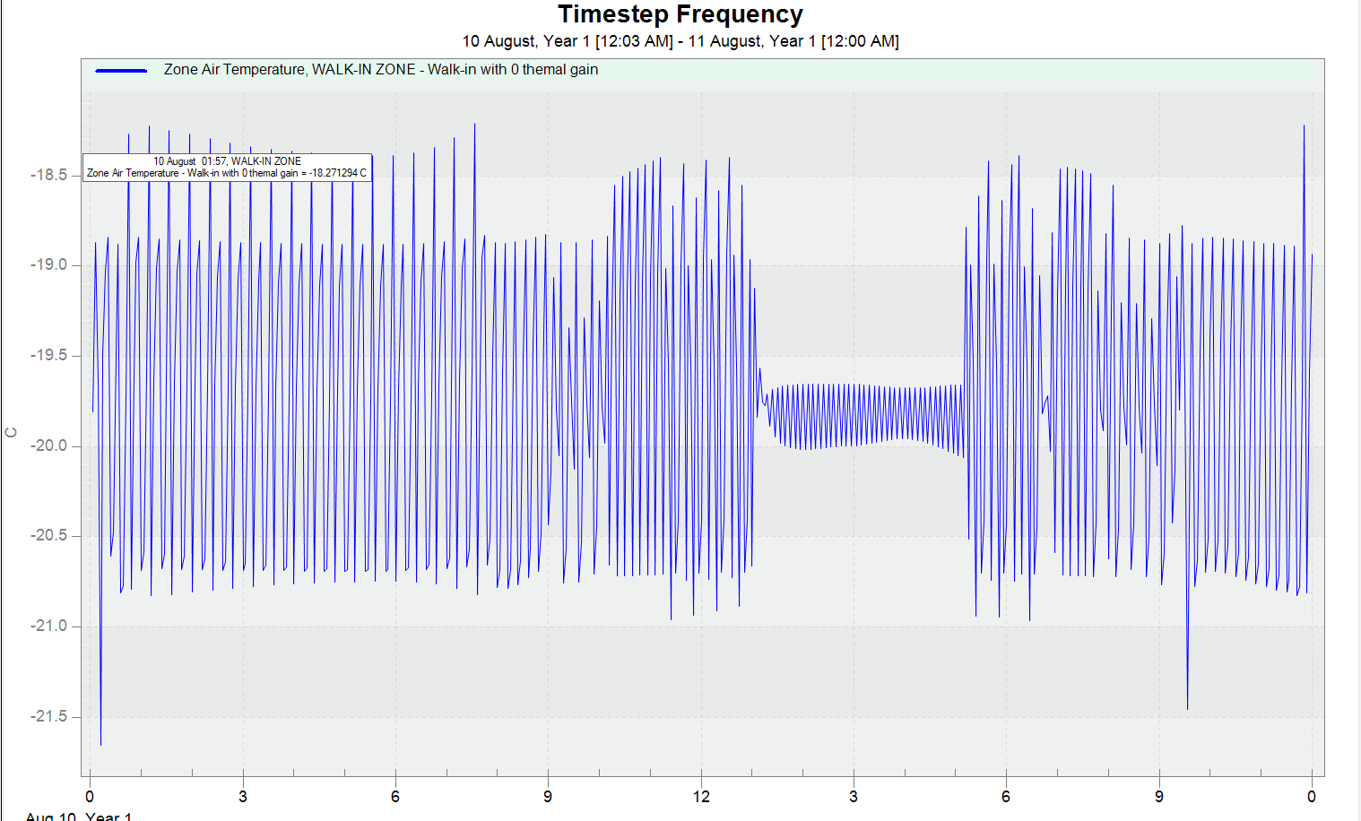
I then changed the value of the temperature difference between cutoff and setpoint to 3C and the result was not what I expected (figure below), as you can see, the temperature fluctuations are not steady and the temperature does not reach the two defined values -18°C and -22°C.
UPDATES
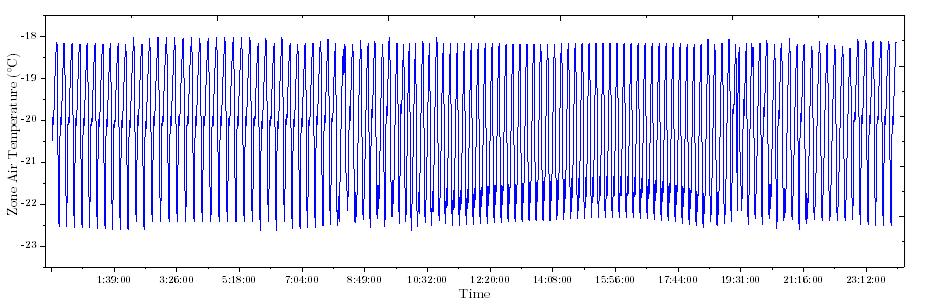
This is the result after I changed the outputs frequency from Timestep to Detailed.
@Zakaria what is the heating setpoint temperature for the thermostat? It's hard to tell from just the zone air temperature if the cooling system or heating system is turning on.
Also, you can try plotting outputs at a Detailed frequency instead of Timestep frequency, which captures the variable timestep EnergyPlus uses to iterate when zone air temperature changes >0.3C within a single model timestep.
It would be good to also plot output variables for heating/cooling thermostat setpoint temperatures as well as air chiller energy and heating component energy for this walk-in zone to help troubleshoot what's going on. You can also save your input file to Dropbox, Google Drive, etc. and share a link so that others can review your model inputs.
Thank you @Boranian for your answer it is really helpful.
I did plot the outputs at Detailed frequency as you suggest and it gives more resonable results (Figure above in the answer area). Could you please explaine what is the deffrent between the 2 output frequencies.
Also since it is a freezer I think that the heating setpoint won't be necessary and I should use ThermostatSetpoint:SingleCooling as Control Object instead of ThermostatSetpoint:DualSetpoint which contain the heating/cooling.
I have edited the the cutout temperature(from 4°C to 3.8°C) to match the ±2°C required. The results are shown in Fig.3 above. The temperature fluctuations does not exactly reach -18°C, also goes down below -20°C even if the heating/cooling setpoints are set to be -20 and -18°C respectevly.
Please start posting anonymously - your entry will be published after you log in or create a new account.
Asked: 2023-01-09 16:22:25 -0500
Seen: 698 times
Last updated: Mar 29 '23


