Question-and-Answer Resource for the Building Energy Modeling Community
Get started with the Help page
Ask Your Question
1

Energyplus connection error to zone

asked 2020-12-27 00:08:19 -0500

Cold wong's avatar

updated 2020-12-28 12:08:47 -0500

My model can run completely, but when I see svg file. It's not a good connection.Like this: image description 
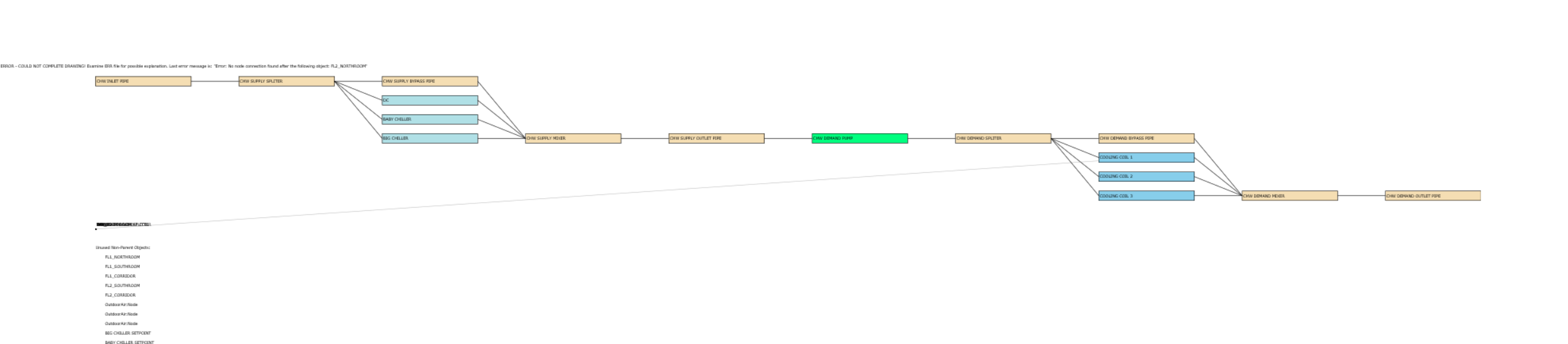
some of my object have listed.

AirTerminal:SingleDuct:VAV:Reheat,
VAV_A1,                  !- Name
All On,                  !- Availability Schedule Name
VAV_A1 Box Damper Node,  !- Damper Air Outlet Node Name
VAV_A1 Box Inlet Node,   !- Air Inlet Node Name
autosize,                !- Maximum Air Flow Rate {m3/s}
Constant,                !- Zone Minimum Air Flow Input Method
autosize,                !- Constant Minimum Air Flow Fraction
,                        !- Fixed Minimum Air Flow Rate {m3/s}
,                        !- Minimum Air Flow Fraction Schedule Name
Coil:Heating:Water,      !- Reheat Coil Object Type
VAV_A1 Box Reheat Coil,  !- Reheat Coil Name
autosize,                !- Maximum Hot Water or Steam Flow Rate {m3/s}
0,                       !- Minimum Hot Water or Steam Flow Rate {m3/s}
VAV_A1 Box outlet node,  !- Air Outlet Node Name
0.001,                   !- Convergence Tolerance
Reverse,                 !- Damper Heating Action
autosize,                !- Maximum Flow per Zone Floor Area During Reheat {m3/s-m2}
autosize;                !- Maximum Flow Fraction During Reheat
ZoneHVAC:AirDistributionUnit,
VAV_A1 BOX,              !- Name
VAV_A1 Box outlet node,  !- Air Distribution Unit Outlet Node Name
AirTerminal:SingleDuct:VAV:Reheat,  !- Air Terminal Object Type
VAV_A1;                  !- Air Terminal Name
ZoneHVAC:EquipmentList,
F1_Northroom Equipment,  !- Name
SequentialLoad,          !- Load Distribution Scheme
ZoneHVAC:AirDistributionUnit,  !- Zone Equipment 1 Object Type
VAV_C1 BOX,              !- Zone Equipment 1 Name
1,                       !- Zone Equipment 1 Cooling Sequence
1,                       !- Zone Equipment 1 Heating or No-Load Sequence
,                        !- Zone Equipment 1 Sequential Cooling Fraction Schedule Name
,                        !- Zone Equipment 1 Sequential Heating Fraction Schedule Name
ZoneHVAC:AirDistributionUnit,  !- Zone Equipment 2 Object Type
VAV_C2 BOX,              !- Zone Equipment 2 Name
2,                       !- Zone Equipment 2 Cooling Sequence
2;                       !- Zone Equipment 2 Heating or No-Load Sequence
ZoneHVAC:EquipmentConnections,
FL1_Northroom,           !- Zone Name
F1_Northroom Equipment,  !- Zone Conditioning Equipment List Name
F1_Northroom VAV List,   !- Zone Air Inlet Node or NodeList Name
,                        !- Zone Air Exhaust Node or NodeList Name
Zone F1_N Air node,      !- Zone Air Node Name
Zone F1_N return air node;  !- Zone Return Air Node or NodeList Name

Any help would be appreciated

edit retag flag offensive close merge delete

Comments

1

While this may indicate a problem with your input file, HVAC-Diagram does not always produce a proper diagram for any possible configuration that EnergyPlus would accept. The diagrams should be viewed as an aid but not as a test for a well-formed HVAC system.

JasonGlazer's avatar JasonGlazer  ( 2020-12-29 09:57:30 -0500 )edit

Thanks, jason. How can I know that I have a well-formed HVAC system?

Cold wong's avatar Cold wong  ( 2020-12-29 22:18:43 -0500 )edit

1 Answer

Sort by ยป oldest newest most voted
0

answered 2020-12-28 12:45:45 -0500

updated 2020-12-28 12:46:43 -0500

The top line of text in your screenshot above the chilled water SVG diagram says:

ERROR - COULD NOT COMPLETE DRAWING! Examine ERR file for possible explanation. Last error message is: "Error: No node connection found after the following object: FL2_NORTHROOM"

This means that in the EnergyPlus input file ending in IDF, the lines below the object named FL2_NORTHROOM (likely a Zone object) do not have node connections defined.

Since the chilled water diagram is rendering correctly in the SVG file, the node connections to air systems and equipment are likely not defined correctly. For example, COOLING COIL 1 has a pair of inlet/outlet nodes for the chilled water loop AND another pair of inlet/outlet nodes for the air loop (central air handler, e.g.) or equipment (zone fan coil unit, e.g.).

For more information, the SVG file is created by the HVAC-Diagram auxiliary program from the BND file (branch and node connections). You could also review the BND file to see where node connections are incorrect.

Just because your model completed the simulation doesn't mean that the model is defined correctly. You should review the error file ending in ERR created by EnergyPlus to see if there are also related warnings or severe errors for node connections.

edit flag offensive delete link more

Comments

I'll check it. Maybe it's hard. Thanks Aaron!

Cold wong's avatar Cold wong  ( 2020-12-29 22:22:38 -0500 )edit

Your Answer

Please start posting anonymously - your entry will be published after you log in or create a new account.

Add Answer

Careers

Question Tools

2 followers

Stats

Asked: 2020-12-27 00:08:19 -0500

Seen: 311 times

Last updated: Dec 28 '20