You may have already been convinced. Probably the most concise answer can be found in InputOutputReference as well.
Section 2.2.19.1.13 Field: Heating Coil Type says "The default value is None. Note that the confguration of HVACTemplate:System:VAV assumes that there will be reheat coils or baseboard heating to provide heating control at the zone level. If a heating coil is specifed, the heating and cooling coil setpoint controls and availability schedules must coordinate to prevent the coils from opposing each other."
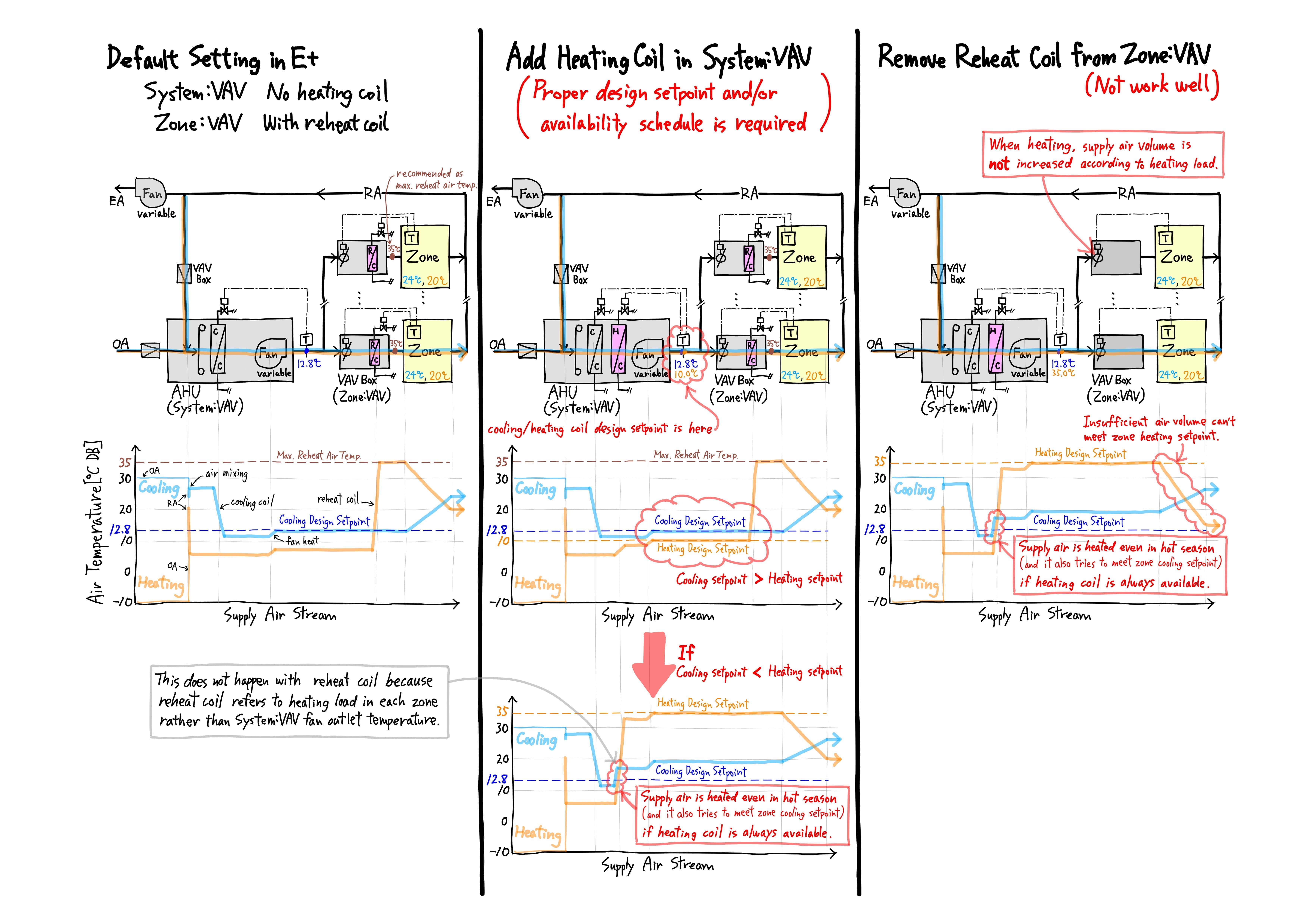
Also, please refer to my sketch. It's my understanding. It has air-side schematic diagrams and changes in supply air temperature for 3 different cases with different heating system. I think the point is the difference in air temperature location that each coil uses for control.
The chart at the bottom center of my sketch shows that if heating coil setpoint is higher than cooling coil setpoint and heating coil is always available, the supply air is heated even in summer. The VAV system uses unnecessary heating energy. The system tries to meet zone cooling setpoint, so the supply air is not fully heated to the heating coil design setpoint, but often the zone cooling setpoint is not met.
I found that the case on the right (HVACTemplate:System:VAV with heating coil + HVACTemplate:Zone:VAV without reheat coil) didn't work well when heating. Therefore, even if your project has AHU with heating coil + VAV box without reheat coil, I think you had better model it like the case on the left (HVACTemplate:System:VAV without heating coil + HVACTemplate:Zone:VAV with reheat coil).
In InputOutputReference, section 2.2.19.1.16 Field: Heating Coil Design Setpoint says that Heating Coil Design Setpoint is used for sizing the heating coil and zone supply air fow rates, but I don't think it's used for sizing zone supply air flow rates. Instead, Zone Heating Design Supply Air Temperature in HVACTemplate:Zone:VAV seems to be used for sizing zone supply air flow rates. Besides, section 2.2.19.1.13 Field: Heating Coil Type says that "The heating coil is located in the supply air stream, upstream of the cooling coil and after the outdoor air mixing box.", but it's incorrect. The heating coil is located downstream of the cooling coil.


