The two questions here are 1) how to model, and 2) how to find the cooling loads. The following answers are related to EnergyPlus simulations.
1) how to model - since you mention fan coil units, place 2 fan coil units in each zone, one without outdoor air and the other with outdoor air which maintains either a neutral supply air temperature, slightly cool supply air temperature, or raw outdoor air. The OA fan coil could also be replaced by a zone DOAS system if desired.
2) In EnergyPlus, component sizing is based on both the zone load and the coincident outdoor air load. The zone load is calculated irrespective of the outdoor air load. Regarding the zone load, the zone air flow rate is calculated based on the Sizing:Zone and thermostat temperatures which are used as surrogates for supply/return air temperature in a Q = mCpdT calculation, where Q is known (zone load) and dT is user specified. This air flow rate, and calculated coil entering mixed air conditions based on outdoor air quantities, are then used to calculate a coil capacity. In other words, the impact of outdoor air is included in coil sizing as a calculated coil entering mixed air temperature. If no outdoor air is specified, the mixed air condition is the same as the zone condition. If outdoor air is included in the model, a calculated mixed air temperature is used to size the coil.
The zone loads are reported in the eio file. This text file can be opened using excel with comma delimited import. To exemplify the zone loads, the WindACAuto example file was simulated and shows the design zone loads for cooling and heating. Focusing on the West zone, the blue highlighted cells show the cooling and heating design and user specified loads. The zone loads include lighting, equipment, occupancy, zone infiltration, and zone ventilation and represent the Q in the equation above.

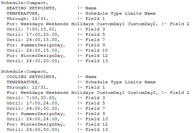
Two objects are required for zone sizing, the thermostat temperatures and the supply air sizing data. In this example file, the zone cooling and heating set point temperatures are entered in the thermostat schedules. The summer and winter design day choices are shown as 24 C and 15 C, with a winter operating temperature of 50 C (off) and 20 C.

The Sizing:Zone object shows the cooling (12 C) and heating (50 C) supply air temperatures. The thermostat temperatures above, those entered for the summer and winter design days, along with the cooling and heating supply air temperatures determine the dT used to calculate zone air flow.

Finally, the difference between the calculated design load and user design load is a result of the multipliers specified in the sizing parameters object. In the first figure above, both the zone loads (blue highlights) and zone air flow rate (red highlights) are adjusted based on these sizing parameters. The user design loads and user design air flow rate are exactly 1.5 times the calculated loads and air flow rates ... (more)


The title and tag are a bit confusing, it seems like an output reporting question, but the main thing you are asking is really how to model this. You may want to update the title. Also please specify what modeling tool you are using.