Question-and-Answer Resource for the Building Energy Modeling Community
First time here? Check out the Help page!
| | 1 | initial version |
The two questions here are 1) how to model, and 2) how to find the cooling loads. The following answers are related to EnergyPlus simulations.
1) how to model - since you mention fan coil units, place 2 fan coil units in each zone, one without outdoor air and the other with outdoor air which maintains either a neutral supply air temperature, slightly cool supply air temperature, or raw outdoor air. The OA fan coil could also be replaced by a zone DOAS system if desired.
2) In EnergyPlus, component sizing is based on both the zone load and the coincident outdoor air load. The zone load is calculated irrespective of the outdoor air load. Regarding the zone load, the zone air flow rate is calculated based on the Sizing:Zone and thermostat temperatures which are used as surrogates for supply/return air temperature in a Q = mCpdT calculation, where Q is known (zone load) and dT is user specified. This air flow rate, and calculated coil entering mixed air conditions based on outdoor air quantities, are then used to calculate a coil capacity. In other words, the impact of outdoor air is included in coil sizing as a calculated coil entering mixed air temperature. If no outdoor air is specified, the mixed air condition is the same as the zone condition. If outdoor air is included in the model, a calculated mixed air temperature is used to size the coil.
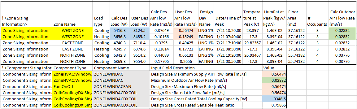
The zone loads are reported in the eio file. This text file can be opened using excel with comma delimited import. To exemplify the zone loads, the WindACAuto example file was simulated and shows the design zone loads for cooling and heating. Focusing on the West zone, the blue highlighted cells show the cooling and heating design and user specified loads. The zone loads include lighting, equipment, occupancy, zone infiltration, and zone ventilation and represent the Q in the equation above.
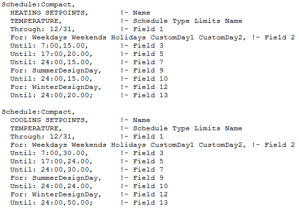
Two objects are required for zone sizing, the thermostat temperatures and the supply air sizing data. In this example file, the zone cooling and heating set point temperatures are entered in the thermostat schedules. The summer and winter design day choices are shown as 24 C and 15 C, with a winter operating temperature of 50 C (off) and 20 C.
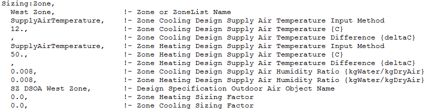
The Sizing:Zone object shows the cooling and heating supply air temperatures. The thermostat temperatures above, those entered for the summer and winter design days, along with the cooling and heating supply air temperatures determine the dT used to calculate zone air flow.
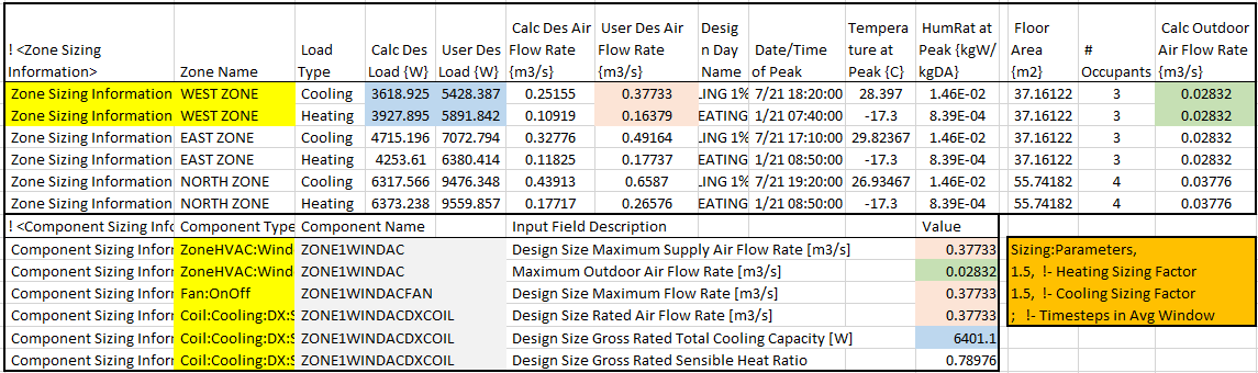
Finally, the difference between the calculated design load and user design load is a result of the multipliers specified in the sizing parameters object. In the first figure above, both the zone loads (blue highlights) and zone air flow rate (red highlights) are adjusted based on these sizing parameters. The user design loads and user design air flow rate are exactly 1.5 times the calculated loads and air flow rates.
Sizing:Parameters,
  1.5,                     !- Heating Sizing Factor
  1.5,                     !- Cooling Sizing Factor
  ;                          !- Timesteps in Averaging Window
To show how the zone loads would change based on a change in zone equipment loads, the West zone ElectricEquipment object was modified to reduce this load by 2000 W.
ElectricEquipment,
  West Zone ElecEq 1,      !- Name
  West Zone,               !- Zone or ZoneList Name
  Intermittent,            !- Schedule Name
  EquipmentLevel,          !- Design Level Calculation Method
  !    2928.751,                !- Design Level {W}
  928.751,                !- Design Level {W}
  ,                        !- Watts per Zone Floor Area {W/m2}
  ,                        !- Watts per Person {W/person}
  0,                       !- Fraction Latent
  0.3000000,               !- Fraction Radiant
  0;                       !- Fraction Lost
The result of this change is a reduction in zone cooling load, of approximately 2000 W, and a slight increase in zone heating load. The reason the zone heating load did not change appreciably is that the ElectricEquipment schedule called for only 15% of the equipment load for the heating design day. Note here that this change also affected other zone load calculations.
Schedule:Compact,
  Intermittent,            !- Name
  ANY NUMBER,              !- Schedule Type Limits Name
  Through: 12/31,          !- Field 1
  For: Weekdays,           !- Field 2
  Until: 8:00,0.00,        !- Field 3
  Until: 18:00,1.00,       !- Field 5
  Until: 24:00,0.00,       !- Field 7
  For: Weekends Holidays CustomDay1 CustomDay2, !- Field 9
  Until: 24:00,0.00,       !- Field 10
  For: SummerDesignDay,    !- Field 12
  Until: 24:00,1.00,       !- Field 13
  For: WinterDesignDay,    !- Field 15
  Until: 24:00,0.15;       !- Field 16
Finally, the outdoor air flow rate (green highlights in figures) is calculated based on the user specified outdoor air quantity for this specific zone. A per person OA flow rate of 0.00944 m3/s/person, multiplied by 3 people (people schedule = 1 for cooling design day), equals 0.02832 m3/s of outdoor air for the west zone (which is the greater of the cooling and heating outdoor air flow rates).
DesignSpecification:OutdoorAir,
  SZ DSOA West Zone,       !- Name
  flow/person,             !- Outdoor Air Method
  0.00944,                 !- Outdoor Air Flow per Person {m3/s-person}
  0.0,                     !- Outdoor Air Flow per Zone Floor Area {m3/s-m2}
  0.0;                     !- Outdoor Air Flow per Zone {m3/s}

People,
  West Zone,               !- Name
  West Zone,               !- Zone or ZoneList Name
  Office Occupancy,        !- Number of People Schedule Name
  people,                  !- Number of People Calculation Method
  3.000000,                !- Number of People

Schedule:Compact,
  Office Occupancy,        !- Name
  ANY NUMBER,              !- Schedule Type Limits Name
  Through: 12/31,          !- Field 1
  For: Weekdays,           !- Field 2
  Until: 6:00,0.00,        !- Field 3
  Until: 7:00,0.10,        !- Field 5
  Until: 8:00,0.50,        !- Field 7
  Until: 12:00,1.00,       !- Field 9
  Until: 13:00,0.50,       !- Field 11
  Until: 16:00,1.00,       !- Field 13
  Until: 17:00,0.50,       !- Field 15
  Until: 18:00,0.10,       !- Field 17
  Until: 24:00,0.00,       !- Field 19
  For: Weekends Holidays CustomDay1 CustomDay2, !- Field 21
  Until: 24:00,0.00,       !- Field 22
  For: SummerDesignDay,    !- Field 24
  Until: 24:00,1.00,       !- Field 25
  For: WinterDesignDay,    !- Field 27
  Until: 24:00,5.00E-002;  !- Field 28
The outdoor air coil sizes are based on this OA flow rate. One caveat to keep in mind, is that sizing will automatically size a zone coil based on the zone load AND the outdoor air flow rate (which impacts the coil entering air temperature used for sizing), so automating the sizing of fan coils, one without outdoor air, and one with is not currently supported. This means that both fan coil units will try to autosize the coils based on the same zone loads and outdoor air quantities. A better method for sizing is to use a fan coil to meet only the zone load, and a zone DOAS to treat (or not) the outdoor air load.
| | 2 | No.2 Revision |
The two questions here are 1) how to model, and 2) how to find the cooling loads. The following answers are related to EnergyPlus simulations.
1) how to model - since you mention fan coil units, place 2 fan coil units in each zone, one without outdoor air and the other with outdoor air which maintains either a neutral supply air temperature, slightly cool supply air temperature, or raw outdoor air. The OA fan coil could also be replaced by a zone DOAS system if desired.
2) In EnergyPlus, component sizing is based on both the zone load and the coincident outdoor air load. The zone load is calculated irrespective of the outdoor air load. Regarding the zone load, the zone air flow rate is calculated based on the Sizing:Zone and thermostat temperatures which are used as surrogates for supply/return air temperature in a Q = mCpdT calculation, where Q is known (zone load) and dT is user specified. This air flow rate, and calculated coil entering mixed air conditions based on outdoor air quantities, are then used to calculate a coil capacity. In other words, the impact of outdoor air is included in coil sizing as a calculated coil entering mixed air temperature. If no outdoor air is specified, the mixed air condition is the same as the zone condition. If outdoor air is included in the model, a calculated mixed air temperature is used to size the coil.
The zone loads are reported in the eio file. This text file can be opened using excel with comma delimited import. To exemplify the zone loads, the WindACAuto example file was simulated and shows the design zone loads for cooling and heating. Focusing on the West zone, the blue highlighted cells show the cooling and heating design and user specified loads. The zone loads include lighting, equipment, occupancy, zone infiltration, and zone ventilation and represent the Q in the equation above.
Two objects are required for zone sizing, the thermostat temperatures and the supply air sizing data. In this example file, the zone cooling and heating set point temperatures are entered in the thermostat schedules. The summer and winter design day choices are shown as 24 C and 15 C, with a winter operating temperature of 50 C (off) and 20 C.
The Sizing:Zone object shows the cooling (12 C) and heating (50 C) supply air temperatures. The thermostat temperatures above, those entered for the summer and winter design days, along with the cooling and heating supply air temperatures determine the dT used to calculate zone air flow.
Finally, the difference between the calculated design load and user design load is a result of the multipliers specified in the sizing parameters object. In the first figure above, both the zone loads (blue highlights) and zone air flow rate (red highlights) are adjusted based on these sizing parameters. The user design loads and user design air flow rate are exactly 1.5 times the calculated loads and air flow rates.
Sizing:Parameters,
  1.5,                     !- Heating Sizing Factor
  1.5,                     !- Cooling Sizing Factor
  ;                          !- Timesteps in Averaging Window
To show how the zone loads would change based on a change in zone equipment loads, the West zone ElectricEquipment object was modified to reduce this load by 2000 W.
ElectricEquipment,
  West Zone ElecEq 1,      !- Name
  West Zone,               !- Zone or ZoneList Name
  Intermittent,            !- Schedule Name
  EquipmentLevel,          !- Design Level Calculation Method
  !    2928.751,                !- Design Level {W}
  928.751,                !- Design Level {W}
  ,                        !- Watts per Zone Floor Area {W/m2}
  ,                        !- Watts per Person {W/person}
  0,                       !- Fraction Latent
  0.3000000,               !- Fraction Radiant
  0;                       !- Fraction Lost
The result of this change is a reduction in zone cooling load, of approximately 2000 W, and a slight increase in zone heating load. The reason the zone heating load did not change appreciably is that the ElectricEquipment schedule called for only 15% of the equipment load for the heating design day. Note here that this change also affected other zone load calculations.
Schedule:Compact,
  Intermittent,            !- Name
  ANY NUMBER,              !- Schedule Type Limits Name
  Through: 12/31,          !- Field 1
  For: Weekdays,           !- Field 2
  Until: 8:00,0.00,        !- Field 3
  Until: 18:00,1.00,       !- Field 5
  Until: 24:00,0.00,       !- Field 7
  For: Weekends Holidays CustomDay1 CustomDay2, !- Field 9
  Until: 24:00,0.00,       !- Field 10
  For: SummerDesignDay,    !- Field 12
  Until: 24:00,1.00,       !- Field 13
  For: WinterDesignDay,    !- Field 15
  Until: 24:00,0.15;       !- Field 16
Finally, the outdoor air flow rate (green highlights in figures) is calculated based on the user specified outdoor air quantity for this specific zone. A per person OA flow rate of 0.00944 m3/s/person, multiplied by 3 people (people schedule = 1 for cooling design day), equals 0.02832 m3/s of outdoor air for the west zone (which is the greater of the cooling and heating outdoor air flow rates).
DesignSpecification:OutdoorAir,
  SZ DSOA West Zone,       !- Name
  flow/person,             !- Outdoor Air Method
  0.00944,                 !- Outdoor Air Flow per Person {m3/s-person}
  0.0,                     !- Outdoor Air Flow per Zone Floor Area {m3/s-m2}
  0.0;                     !- Outdoor Air Flow per Zone {m3/s}

People,
  West Zone,               !- Name
  West Zone,               !- Zone or ZoneList Name
  Office Occupancy,        !- Number of People Schedule Name
  people,                  !- Number of People Calculation Method
  3.000000,                !- Number of People

Schedule:Compact,
  Office Occupancy,        !- Name
  ANY NUMBER,              !- Schedule Type Limits Name
  Through: 12/31,          !- Field 1
  For: Weekdays,           !- Field 2
  Until: 6:00,0.00,        !- Field 3
  Until: 7:00,0.10,        !- Field 5
  Until: 8:00,0.50,        !- Field 7
  Until: 12:00,1.00,       !- Field 9
  Until: 13:00,0.50,       !- Field 11
  Until: 16:00,1.00,       !- Field 13
  Until: 17:00,0.50,       !- Field 15
  Until: 18:00,0.10,       !- Field 17
  Until: 24:00,0.00,       !- Field 19
  For: Weekends Holidays CustomDay1 CustomDay2, !- Field 21
  Until: 24:00,0.00,       !- Field 22
  For: SummerDesignDay,    !- Field 24
  Until: 24:00,1.00,       !- Field 25
  For: WinterDesignDay,    !- Field 27
  Until: 24:00,5.00E-002;  !- Field 28
The outdoor air coil sizes are based on this OA flow rate. One caveat to keep in mind, is that sizing will automatically size a zone coil based on the zone load AND the outdoor air flow rate (which impacts the coil entering air temperature used for sizing), so automating the sizing of fan coils, one without outdoor air, and one with is not currently supported. This means that both fan coil units will try to autosize the coils based on the same zone loads and outdoor air quantities. A better method for sizing is to use a fan coil to meet only the zone load, and a zone DOAS to treat (or not) the outdoor air load.
| | 3 | No.3 Revision |
The two questions here are 1) how to model, and 2) how to find the cooling loads. The following answers are related to EnergyPlus simulations.
1) how to model - since you mention fan coil units, place 2 fan coil units in each zone, one without outdoor air and the other with outdoor air which maintains either a neutral supply air temperature, slightly cool supply air temperature, or raw outdoor air. The OA fan coil could also be replaced by a zone DOAS system if desired.
2) In EnergyPlus, component sizing is based on both the zone load and the coincident outdoor air load. The zone load is calculated irrespective of the outdoor air load. Regarding the zone load, the zone air flow rate is calculated based on the Sizing:Zone and thermostat temperatures which are used as surrogates for supply/return air temperature in a Q = mCpdT calculation, where Q is known (zone load) and dT is user specified. This air flow rate, and calculated coil entering mixed air conditions based on outdoor air quantities, are then used to calculate a coil capacity. In other words, the impact of outdoor air is included in coil sizing as a calculated coil entering mixed air temperature. If no outdoor air is specified, the mixed air condition is the same as the zone condition. If outdoor air is included in the model, a calculated mixed air temperature is used to size the coil.
The zone loads are reported in the eio file. This text file can be opened using excel with comma delimited import. To exemplify the zone loads, the WindACAuto example file was simulated and shows the design zone loads for cooling and heating. Focusing on the West zone, the blue highlighted cells show the cooling and heating design and user specified loads. The zone loads include lighting, equipment, occupancy, zone infiltration, and zone ventilation and represent the Q in the equation above.
Two objects are required for zone sizing, the thermostat temperatures and the supply air sizing data. In this example file, the zone cooling and heating set point temperatures are entered in the thermostat schedules. The summer and winter design day choices are shown as 24 C and 15 C, with a winter operating temperature of 50 C (off) and 20 C.
The Sizing:Zone object shows the cooling (12 C) and heating (50 C) supply air temperatures. The thermostat temperatures above, those entered for the summer and winter design days, along with the cooling and heating supply air temperatures determine the dT used to calculate zone air flow.
Finally, the difference between the calculated design load and user design load is a result of the multipliers specified in the sizing parameters object. In the first figure above, both the zone loads (blue highlights) and zone air flow rate (red highlights) are adjusted based on these sizing parameters. The user design loads and user design air flow rate are exactly 1.5 times the calculated loads and air flow rates.
Sizing:Parameters,
  1.5,                     !- Heating Sizing Factor
  1.5,                     !- Cooling Sizing Factor
  ;                          !- Timesteps in Averaging Window
To show how the zone loads would change based on a change in zone equipment loads, the West zone ElectricEquipment object was modified to reduce this load by 2000 W.
ElectricEquipment,
  West Zone ElecEq 1,      !- Name
  West Zone,               !- Zone or ZoneList Name
  Intermittent,            !- Schedule Name
  EquipmentLevel,          !- Design Level Calculation Method
  !    2928.751,                !- Design Level {W}
  928.751,                !- Design Level {W}
  ,                        !- Watts per Zone Floor Area {W/m2}
  ,                        !- Watts per Person {W/person}
  0,                       !- Fraction Latent
  0.3000000,               !- Fraction Radiant
  0;                       !- Fraction Lost
The result of this change is a reduction in zone cooling load, of approximately 2000 W, and a slight increase in zone heating load. The reason the zone heating load did not change appreciably is that the ElectricEquipment schedule called for only 15% of the equipment load for the heating design day. Note here that this change also affected other zone load calculations.
Schedule:Compact,
  Intermittent,            !- Name
  ANY NUMBER,              !- Schedule Type Limits Name
  Through: 12/31,          !- Field 1
  For: Weekdays,           !- Field 2
  Until: 8:00,0.00,        !- Field 3
  Until: 18:00,1.00,       !- Field 5
  Until: 24:00,0.00,       !- Field 7
  For: Weekends Holidays CustomDay1 CustomDay2, !- Field 9
  Until: 24:00,0.00,       !- Field 10
  For: SummerDesignDay,    !- Field 12
  Until: 24:00,1.00,       !- Field 13
  For: WinterDesignDay,    !- Field 15
  Until: 24:00,0.15;       !- Field 16
Finally, the outdoor air flow rate (green highlights in figures) is calculated based on the user specified outdoor air quantity for this specific zone. A per person OA flow rate of 0.00944 m3/s/person, multiplied by 3 people (people schedule = 1 for cooling design day), equals 0.02832 m3/s of outdoor air for the west zone (which is the greater of the cooling and heating outdoor air flow rates).
DesignSpecification:OutdoorAir,
  SZ DSOA West Zone,       !- Name
  flow/person,             !- Outdoor Air Method
  0.00944,                 !- Outdoor Air Flow per Person {m3/s-person}
  0.0,                     !- Outdoor Air Flow per Zone Floor Area {m3/s-m2}
  0.0;                     !- Outdoor Air Flow per Zone {m3/s}

People,
  West Zone,               !- Name
  West Zone,               !- Zone or ZoneList Name
  Office Occupancy,        !- Number of People Schedule Name
  people,                  !- Number of People Calculation Method
  3.000000,                !- Number of People

Schedule:Compact,
  Office Occupancy,        !- Name
  ANY NUMBER,              !- Schedule Type Limits Name
  Through: 12/31,          !- Field 1
  For: Weekdays,           !- Field 2
  Until: 6:00,0.00,        !- Field 3
  Until: 7:00,0.10,        !- Field 5
  Until: 8:00,0.50,        !- Field 7
  Until: 12:00,1.00,       !- Field 9
  Until: 13:00,0.50,       !- Field 11
  Until: 16:00,1.00,       !- Field 13
  Until: 17:00,0.50,       !- Field 15
  Until: 18:00,0.10,       !- Field 17
  Until: 24:00,0.00,       !- Field 19
  For: Weekends Holidays CustomDay1 CustomDay2, !- Field 21
  Until: 24:00,0.00,       !- Field 22
  For: SummerDesignDay,    !- Field 24
  Until: 24:00,1.00,       !- Field 25
  For: WinterDesignDay,    !- Field 27
  Until: 24:00,5.00E-002;  !- Field 28
The outdoor air coil sizes are based on this OA flow rate. One caveat to keep in mind, is that sizing will automatically size a zone coil based on the zone load AND the outdoor air flow rate (which impacts the coil entering air temperature used for sizing), so automating the sizing of fan coils, one without outdoor air, and one with is not currently supported. This means that both fan coil units will try to autosize the coils based on the same zone loads and outdoor air quantities. A better method for sizing is to use a fan coil to meet only the zone load, and a zone DOAS to treat (or not) the outdoor air load.load (see ZoneHVAC:OutdoorAirUnit).
| | 4 | No.4 Revision |
The two questions here are 1) how to model, and 2) how to find the cooling loads. The following answers are related to EnergyPlus simulations.
1) how to model - since you mention fan coil units, place 2 fan coil units in each zone, one without outdoor air and the other with outdoor air which maintains either a neutral supply air temperature, slightly cool supply air temperature, or raw outdoor air. The OA fan coil could also be replaced by a zone DOAS system if desired.
2) In EnergyPlus, component sizing is based on both the zone load and the coincident outdoor air load. The zone load is calculated irrespective of the outdoor air load. Regarding the zone load, the zone air flow rate is calculated based on the Sizing:Zone and thermostat temperatures which are used as surrogates for supply/return air temperature in a Q = mCpdT calculation, where Q is known (zone load) and dT is user specified. This air flow rate, and calculated coil entering mixed air conditions based on outdoor air quantities, are then used to calculate a coil capacity. In other words, the impact of outdoor air is included in coil sizing as a calculated coil entering mixed air temperature. If no outdoor air is specified, the mixed air condition is the same as the zone condition. If outdoor air is included in the model, a calculated mixed air temperature is used to size the coil.
The zone loads are reported in the eio file. This text file can be opened using excel with comma delimited import. To exemplify the zone loads, the WindACAuto example file was simulated and shows the design zone loads for cooling and heating. Focusing on the West zone, the blue highlighted cells show the cooling and heating design and user specified loads. The zone loads include lighting, equipment, occupancy, zone infiltration, and zone ventilation and represent the Q in the equation above.
Two objects are required for zone sizing, the thermostat temperatures and the supply air sizing data. In this example file, the zone cooling and heating set point temperatures are entered in the thermostat schedules. The summer and winter design day choices are shown as 24 C and 15 C, with a winter operating temperature of 50 C (off) and 20 C.
The Sizing:Zone object shows the cooling (12 C) and heating (50 C) supply air temperatures. The thermostat temperatures above, those entered for the summer and winter design days, along with the cooling and heating supply air temperatures determine the dT used to calculate zone air flow.
Finally, the difference between the calculated design load and user design load is a result of the multipliers specified in the sizing parameters object. In the first figure above, both the zone loads (blue highlights) and zone air flow rate (red highlights) are adjusted based on these sizing parameters. The user design loads and user design air flow rate are exactly 1.5 times the calculated loads and air flow rates.
Sizing:Parameters,
  1.5,                     !- Heating Sizing Factor
  1.5,                     !- Cooling Sizing Factor
  ;                          !- Timesteps in Averaging Window
To show how the zone loads would change based on a change in zone equipment loads, the West zone ElectricEquipment object was modified to reduce this load by 2000 W.
ElectricEquipment,
  West Zone ElecEq 1,      !- Name
  West Zone,               !- Zone or ZoneList Name
  Intermittent,            !- Schedule Name
  EquipmentLevel,          !- Design Level Calculation Method
  !    2928.751,                !- Design Level {W}
  928.751,                !- Design Level {W}
  ,                        !- Watts per Zone Floor Area {W/m2}
  ,                        !- Watts per Person {W/person}
  0,                       !- Fraction Latent
  0.3000000,               !- Fraction Radiant
  0;                       !- Fraction Lost
The result of this change is a reduction in zone cooling load, of approximately 2000 W, and a slight increase in zone heating load. The reason the zone heating load did not change appreciably is that the ElectricEquipment schedule called for only 15% of the equipment load for the heating design day. Note here that this change also affected other zone load calculations.
Schedule:Compact,
  Intermittent,            !- Name
  ANY NUMBER,              !- Schedule Type Limits Name
  Through: 12/31,          !- Field 1
  For: Weekdays,           !- Field 2
  Until: 8:00,0.00,        !- Field 3
  Until: 18:00,1.00,       !- Field 5
  Until: 24:00,0.00,       !- Field 7
  For: Weekends Holidays CustomDay1 CustomDay2, !- Field 9
  Until: 24:00,0.00,       !- Field 10
  For: SummerDesignDay,    !- Field 12
  Until: 24:00,1.00,       !- Field 13
  For: WinterDesignDay,    !- Field 15
  Until: 24:00,0.15;       !- Field 16
Finally, the outdoor air flow rate (green highlights in figures) is calculated based on the user specified outdoor air quantity for this specific zone. A per person OA flow rate of 0.00944 m3/s/person, multiplied by 3 people (people schedule = 1 for cooling design day), equals 0.02832 m3/s of outdoor air for the west zone (which is the greater of the cooling and heating outdoor air flow rates).
DesignSpecification:OutdoorAir,
  SZ DSOA West Zone,       !- Name
  flow/person,             !- Outdoor Air Method
  0.00944,                 !- Outdoor Air Flow per Person {m3/s-person}
  0.0,                     !- Outdoor Air Flow per Zone Floor Area {m3/s-m2}
  0.0;                     !- Outdoor Air Flow per Zone {m3/s}

People,
  West Zone,               !- Name
  West Zone,               !- Zone or ZoneList Name
  Office Occupancy,        !- Number of People Schedule Name
  people,                  !- Number of People Calculation Method
  3.000000,                !- Number of People

Schedule:Compact,
  Office Occupancy,        !- Name
  ANY NUMBER,              !- Schedule Type Limits Name
  Through: 12/31,          !- Field 1
  For: Weekdays,           !- Field 2
  Until: 6:00,0.00,        !- Field 3
  Until: 7:00,0.10,        !- Field 5
  Until: 8:00,0.50,        !- Field 7
  Until: 12:00,1.00,       !- Field 9
  Until: 13:00,0.50,       !- Field 11
  Until: 16:00,1.00,       !- Field 13
  Until: 17:00,0.50,       !- Field 15
  Until: 18:00,0.10,       !- Field 17
  Until: 24:00,0.00,       !- Field 19
  For: Weekends Holidays CustomDay1 CustomDay2, !- Field 21
  Until: 24:00,0.00,       !- Field 22
  For: SummerDesignDay,    !- Field 24
  Until: 24:00,1.00,       !- Field 25
  For: WinterDesignDay,    !- Field 27
  Until: 24:00,5.00E-002;  !- Field 28
The outdoor air coil sizes are based on this OA flow rate. rate, however, zone equipment does not include what would be considered an outdoor air coil (only air loops have true outdoor air systems). One caveat to keep in mind, is that sizing will automatically size a zone coil based on the zone load AND the outdoor air flow rate (which impacts the coil entering air temperature used for sizing), so automating the sizing of fan coils, one without outdoor air, and one with is not currently supported. This means that both fan coil units will try to autosize the coils based on the same zone loads and outdoor air quantities. A better method for sizing is to use a fan coil to meet only the zone load, and a zone DOAS to treat (or not) the outdoor air load (see ZoneHVAC:OutdoorAirUnit).


