Question-and-Answer Resource for the Building Energy Modeling Community
Get started with the Help page
Ask Your Question
2

How to configure parallel branch pumps for fan coils in a chiller system

asked 2020-11-02 07:19:10 -0500

Dr. Fan's avatar

updated 2020-11-24 05:55:50 -0500

Hello everyone,

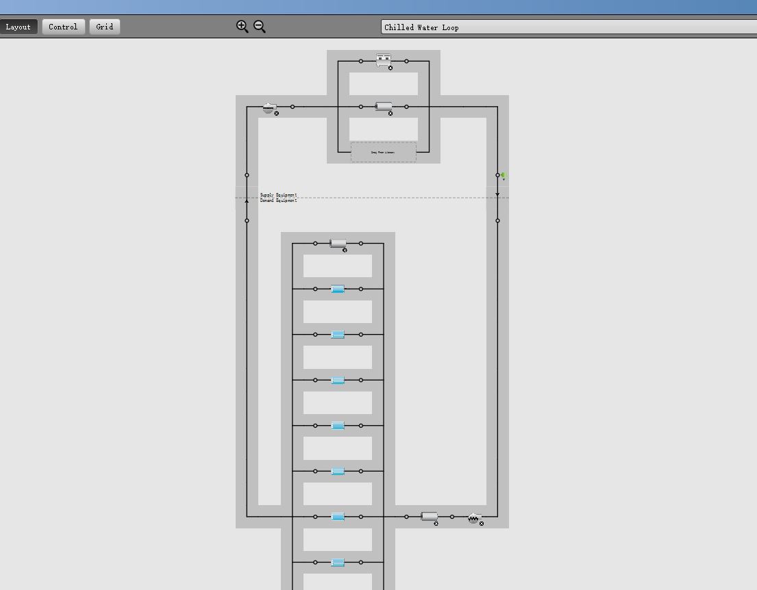
I just developed a primary-secondary chilled water system to provided the chilled water for multiple ZoneHVAC:FourPipeFanCoil that are served as Zone Equipmentsin thermal zones. The current configuration of the system is like the figure as below and i also attach my osm file here for you guys to download https://drive.google.com/file/d/1bjju... : image description.

My question is how to configure my system according to the following figure.

image description

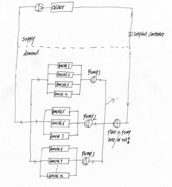
I want to use three pumps to serve the ZoneHVAC:FourPipeFanCoil that are distributed in different parts of a building. For example, the fan coils in 1st-3rd floors will be served by pump 1, and fan coils in 4th-7th floors will be served by pump 2 and fan coils in other floors will be served by pump 3. This configuration is very common in real engineering project, but i did not find a way to add a parallel branch for the fan coils and pumps. I read the Engineering Reference of Energyplus and it seems that only one splitter and mixer is allowed for the supply or demand half loop. Is anyone has an idea on how to handle this issue. Thank you Very much!

edit retag flag offensive close merge delete

2 Answers

Sort by ยป oldest newest most voted
1

answered 2020-11-04 07:52:51 -0500

updated 2020-11-04 07:53:20 -0500

About Q1: I think it's a sizing issue. Click on the dashed line between the supply and demand side, on the right side of your screen, scroll down until you see the sizing parameters. When you add a new loop, by default, openstudio assumes that you're adding a heating loop. So you need to check the temperature setting in sizing:system based on your application.

About Q2: I usually do it by using EMS in E+. I have no idea about Openstudio. Sorry!

About Q3: I think a one-way common pipe is suitable for your application. In fact, it is needed for a flow mismatch between the two half loops (constant speed pump on the primary side and variable speed on the secondary side). An example of using a two-way common pipe is when you have thermal energy storage on the primary side of your cooling loop.

About Q4: Energyplus recommends that you always have a bypass pipe parallel with components in demand or supply branch. If it's not needed, energyplus will figure it out. So you don't have to worry about it.

edit flag offensive delete link more

Comments

Thank you very much, Mehrdad. As you said, the default operation mode for the plant loop sizing is heating mode. After i changed it into cooling model, Q1 was solved.

Dr. Fan's avatar Dr. Fan  ( 2020-11-09 10:12:18 -0500 )edit
0

answered 2020-11-24 15:29:27 -0500

The only way I know of to split out booster pumps like that is to set up separate plant loops and then connect them to your main plant loop using ideal heat exchanger objects. For example your chiller would be on CHWS-1, and presumably your main loop has its own pump for the chiller, so you would have a pump on branch 1 and the chiller on branch 2. Then you would set up CHWS-2, 3 and 4, each with an ideal HX and P-1, 2 and 3 from your drawing, where the HXs connect as the demand of CHWS-1. Then you can assign CHWS-2 to the coils for FCU-1-4, CHWS-3 to FCU-5-7 and CHWS-4 to FCU-8-n.

edit flag offensive delete link more

Your Answer

Please start posting anonymously - your entry will be published after you log in or create a new account.

Add Answer

Careers

Question Tools

3 followers

Stats

Asked: 2020-11-02 07:19:10 -0500

Seen: 671 times

Last updated: Nov 24 '20