why no flow through parts of plant loop?


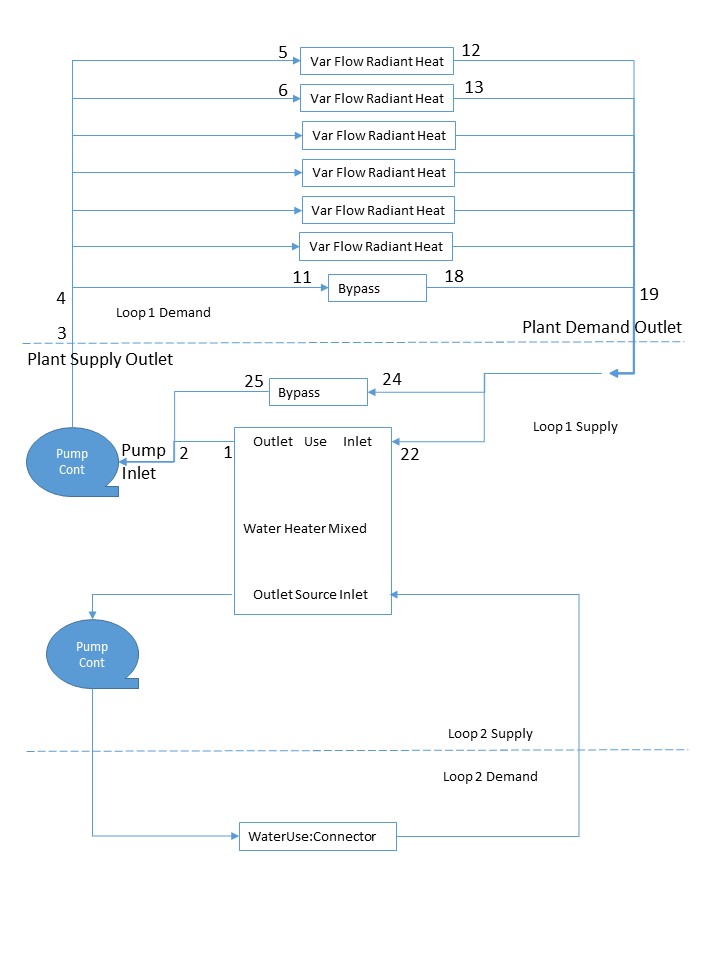
Oh wise ones - newbie user again. In E+, I have set up 2 Plant loops; one for service water uses, the other for radiant floor supply. See diagram. Both loops clear the integrity check and sizing subrountines; and the simulation runs, but I am unable to maintain desired temps in the desired zones. Checking the loop flows and temps, I find Loop 1 (radiant heat loop) demand side flows only through the bypass and one of the radiant floor loops (not the shortest one) while the supply side flows only through the bypass - so no suprise about lack of T control. I have water heaters set at 60C outlet (internal temps check out). Loop1 setpointmanager:scheduled:Dual Setpoint temp (45 deg C max 10deg C min) controlling at the Plant supply outlet node Each of the Radiant floors has its own Thermostat setting schedules varying from 15 to 21. I am running in heating only mode. There is also no flow in the service water loop water heater, though oddly the run summaries show an annual heat duty for the service water (98 GJ for 120 m3) loop, and (8 GJ) (no consumption). The service water loop runs one a single heating setpoint. Pumps are running continuously and auto-sized. I have tried setting the loops on the source side of the water heaters, and also running each loop on a single water water heater (one loop source, and one use) to no effect. Also tried a single heating setpoint for loop one at the high temp.
Any ideas what I am doing wrong?! (i would be happy to post IDF if I could figure out how....) image description...


OK, now that I have moved the pump(s) to the splitter inlet rather than mixer outlet, and put a tempering valve rather than pipe as the bypass branche(s), i get flow through all of the radiant branches, and the relative quantities/and timing make sense based on the heating loads of each of the radiant zones. But I am still not achieving zone temp targets. I have tried switching to variable flow pumps, but the loop total flow volume with either case limits out at the same number. Is this an auto sizing limit problem?
Apologies as this is becoming a learning blog. So I now understand that Autosizing of the radiant component flowrates is also controlled by the SizingPlant object. The loop design delta T is a fixed control- flow rates are limited to ensure that dT thus, if set too large, the flow rates will not be sufficient to ensure enough T transfer to maintain needed temps. This with non-coincident loop sizing. Coincident loop component sizing option didn't appear to change rad. floor tube length or diameter or max flow rates - I need to check what drives this sizing algorithm; may not work for radiant.