Question-and-Answer Resource for the Building Energy Modeling Community
Get started with the Help page
Ask Your Question
1

Radiance scattering through ground glass

asked 2018-04-29 18:41:01 -0500

chris's avatar

updated 2018-04-30 14:17:02 -0500

Hi!

I am doing some tests with Radiance and have some difficulties using light scattered on a sort of ground glass. The setup I am using is quite simple. a ground glass typed plane (gg plane) and another parallel plane in some distance. The gg plane is serving as a virtual light source and I want to verify intensity reduction per area, with the second plane in different distances.

The base setup is as follows:

  • CIE, clear sky with sun, 21 March, 12:00, latitude 0°, longitude 30°(gensky 3 21 12:0GMT -a 30 -o 0 +s).
  • The gg plane is facing directly south, control plane is parallel in different distances, e.g. 2 m and 8 m.

There seems to be no widening in the scattered intensity when the receiving plane is placed e.g. in 2 m and 8 m distance. The light seems to propagate collimated. I would have expected sort of Lambertian scattering from the gg plane, resulting in a reduced intensity / area with increasing distance.

For the gg plane I tried a number of different parameters, e.g.:

void trans e18f205e-4986-4e35-b872-1c0d4d99db44-00031dca

0

0

7 0.48913 0.48913 0.48913 0.08 0 0.5333 0

For the radiance command I also tried a variety of parameters, e.g.:

rtrace -aa 0.15 -ab 4 -ad 256 -ar 32 -as 20 -st 1 -lw 0.05 -dc 0 -dj 0.7 -dp 32 -dr 0 -ds 0

Any help is appreciated! In case it is helpful, I can provide rad, octree, sky and all other files used to run the radiance simulation. Cheers Chris

[EDIT]:

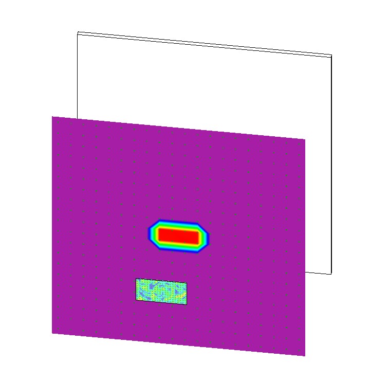
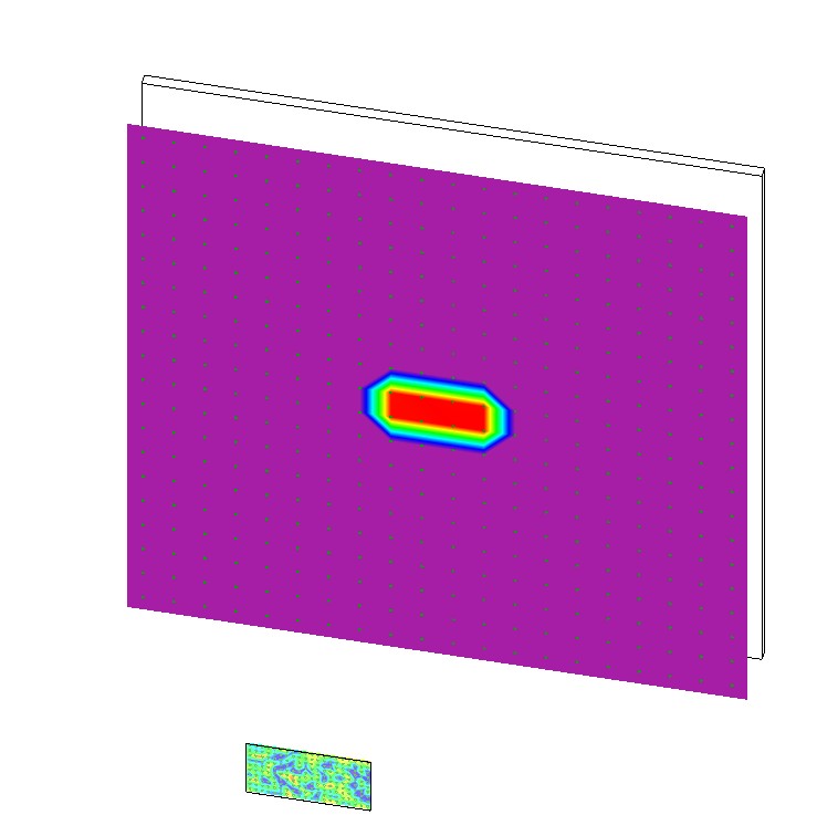
I have uploaded two images here showing more or less the situation. The smaller speckled plane is the ground glass. The larger white plane has a fixed position relative to the ground glass and finally the purple plane is the 'measurement plane'. The 'purple' plane is in false color, showing the intensity distribution. What is remarkable, the intensity distribution does not seem to change with the distance. I hope the images make it a little bit clearer. Of course, this sort of completely artificial test, but I derived it from a more realistic scenario, where the gg plane was used to illuminate a deep room, by boiling things down to the bare minimum.

image description image description

edit retag flag offensive close merge delete

2 Answers

Sort by » oldest newest most voted
2

answered 2018-05-01 11:48:18 -0500

updated 2018-05-10 18:11:05 -0500

Bear in mind that if your two planes are very large with respect to the distance between them, then there should be no change in the incident flux on the second surface with respect to distance. Your surfaces need to be small enough that the open ends start to dominate the cosine-weighted integral for illuminance. This implies that the distance between surfaces is on the order of or greater than the size of the ground glass surface.

That said, there may also be inaccuracies due to irradiance caching in this case, since -aa 0.15 will tend to use nearby values when it doesn't see much of a gradient. You can decrease to -aa 0.02 for a more reliable result. You should also make sure that you are sending enough samples to get a good integral. I would recommend -ad 700 -as 200 or so.

Finally, if you are not using the latest HEAD release, I suggest using -as 0 because I recently discovered and corrected a bias in the ambient super-sampling method that was introduced in version 5.1.

++++ New info: Thanks for posting your files. I used "rtrace -I+ -ab 1 -ad 4096 -aa 0" in my tests. There seem to be two issues with your experiment. The first is that there is nothing keeping your test points from seeing the sun directly, unless it is blocked by the diffuser. Further back points see the sun, so they have a larger value than points nearer to (and thus occluded by) the diffuser. You need a box around your space. All you have is a black wall that sits entirely behind your test points, and is therefore irrelevant.

I strongly recommend visualizing your scene in rvu as a sanity check before doing numerical analyses. This avoids most such issues. It may also help to visualize where your points are in space by replacing them with tiny spheres, as a further check.

To save you from reading through all the comments, the main error was leaving off the -I+ option, which is needed to compute irradiance rather than radiance values. The initial simulation was basically sending parallel rays straight at the window, which of course doesn't change with distance (besides getting completely the wrong answer).

edit flag offensive delete link more

Comments

Hi! Thanks a lot for your reply! I tried the rtrace parameters, but unfortunately it does not change the result (using as 0, as I still have to build the head). Actually I tried to replicate an 'experiment' taken from Rocha: "Avaliação do programa APOLUX segundo protocolos do relatório CIE 171:2006 referentes à iluminação natural" (https://repositorio.ufsc.br/handle/12...). It is the example for parallel planes from the CIE. In that case she modelled a room with an opening of the size of the gg plane and detected the intensity in different distances inside the room.

chris's avatar chris  ( 2018-05-01 13:58:45 -0500 )edit

As the intesity did not decrease with distance I tried this simplified setup, with a smaller gg plane and a quite large receiving plane, to see where the intensity is going. The actual gg plane is 2m x 1m, the distance of the receiving plane is roughly between 2 m and 8 m and in the example I posted the receiving plane is 10 m x 10 m.

chris's avatar chris  ( 2018-05-01 14:00:54 -0500 )edit
1

Dumb question, but I'm assuming you either aren't using an ambient file (-af option) or are discarding it between trials, right? Did you try using "-aa 0" just to eliminate the irradiance cache as a potential problem?

GregWard's avatar GregWard  ( 2018-05-01 14:14:39 -0500 )edit

Right, I don't use an ambient file and setting aa=0 does not seem to affect the results. I have packed the files I use for the simulation together: http://evelisedidone.com/0/cloud/inde...

chris's avatar chris  ( 2018-05-04 07:28:40 -0500 )edit

I downloaded this file, which is tiny, but I cannot unpack it using any of my archiving tools (including 7za). Can you put it in a more common format, like zip, or gzip, or tar, or whatever. Presumably it's just a few text files.

GregWard's avatar GregWard  ( 2018-05-04 11:25:21 -0500 )edit
1

answered 2018-04-29 22:09:26 -0500

Some results might be helpful, e.g. a series of plots of the rtrace data from the different distances. A quick glance of those trans parameters seems to indicate that you have a totally diffuse transmitter; your description of your results and your setup are somewhat confusing to me though. Recommend you make a couple of renderings of a space with a clear glass mat and your trans mat and compare the visual results, in addition to evaluating the point calcs.

edit flag offensive delete link more

Your Answer

Please start posting anonymously - your entry will be published after you log in or create a new account.

Add Answer

Careers

Question Tools

1 follower

Stats

Asked: 2018-04-29 18:41:01 -0500

Seen: 235 times

Last updated: May 10 '18