Question-and-Answer Resource for the Building Energy Modeling Community
Get started with the Help page
Ask Your Question
3

Fan power calculation for variable speed Fan:OnOff

asked 2016-11-04 10:39:51 -0500

updated 2016-11-09 10:43:19 -0500

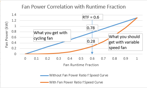
I am modeling a multispeed coil (Coil:Cooling:DX:Multispeed) and a variable speed fan using the Fan:OnOff object (I want it to be able to cycle). According to the documentation, if you wish to model a variable speed fan you need to provide a fan curve that represents the ratio of actual fan power to rated fan power when a change in fan speed occurs. If my understanding of the documentation is correct, for example, if my rated fan power is 1000W and that my fan is running at a PLR of 0.6 and that my curve returns a value of 0.4 my actual fan power should be 400W. I tried with several different curves but I couldn’t get my fan power to be calculated according to my interpretation.

To get a better understanding of what EnergyPlus is doing, I took a quick peek at the source code. I noticed that on line 1926 through 1930 there is an if/else statement that sets the fan run time fraction equals to the part load ratio if “OnOffFanPartLoadFraction” is equal to 1. In the case where my fan’s “OnOffFanPartLoadFRaction” is 1 but is running at a PLR < 1, then the fan runtime fraction used in the fan power calculation is going to be equal to my PLR and used as is in the fan power calculation. I ran hourly reports and for all hours where my fan PLR was < 1 but the fan RTF = 1, I divided the fan power calculated by EnergyPlus by the hourly PLR and got the fan power I was expecting to get, which for the previous example (rated fan power 1000W, at a PLR of 0.6 output of the curve 0.4) EnergyPlus is returning a fan power = 1000 * 0.6 * 0.4, whereas if my understanding of the documentation is correct it should return 1000 * 0.4.

To get what I wanted, I created a new curve based on the regression of the output of my original curve divided by the PLR as a function of the PLR. However, I am still curious to know what is going on, if I am just not interpreting the documentation properly or if there is something going on with the code or if something else in my model could be causing this behavior.

EDIT:

@rraustad: Thank you for providing an explanation of the code. Perhaps my question was not well written because I’m not sure you understood what I am trying to do. In short, I would like the fan power to be calculated using a fan power modifier that is function of the fan part load ratio. In DOE-2, this can be done using the FAN-EIR-FPLR keyword which is defined as follows:

FAN-EIR-FPLR is a “curve that gives the ratio of fan electric energy to full-load fan electric energy, as a function of part-load ratio […]”

In my EnergyPlus model I have to use a Fan:OnOff object since I ... (more)

edit retag flag offensive close merge delete

Comments

You did not say whether you are using the fan efficiency curve and what your exponential curve looks like. The example file PackagedTerminalHeatPump has example fan power:

Curve:Exponent,
FanPowerRatioCurve,      !- Name
0.0,                     !- Coefficient1 Constant
1.0,                     !- Coefficient2 Constant
3.0,                     !- Coefficient3 Constant
0.0,                     !- Minimum Value of x
1.5,                     !- Maximum Value of x
0.01,                    !- Minimum Curve Output
1.5;                     !- Maximum Curve Output
rraustad's avatar rraustad  ( 2016-11-09 10:59:48 -0500 )edit

... and fan efficiency as:

Curve:Cubic,
FanEffRatioCurve,        !- Name
0.33856828,              !- Coefficient1 Constant
1.72644131,              !- Coefficient2 x
-1.49280132,             !- Coefficient3 x**2
0.42776208,              !- Coefficient4 x**3
0.5,                     !- Minimum Value of x
1.5,                     !- Maximum Value of x
0.3,                     !- Minimum Curve Output
1.0;                     !- Maximum Curve Output

P.S. at PLR = 0.4 your curve output is negative. Min PLR should be 0.43333

rraustad's avatar rraustad  ( 2016-11-09 11:01:01 -0500 )edit

I am not using a fan efficiency curve. I am using a minimum curve output of 0.4 to avoid negative values. My exponential curve has C1 = -0.7647, C2 = 1.7647 and C3 = 1.

Jeremy's avatar Jeremy  ( 2016-11-09 11:08:49 -0500 )edit

Email me your idf so I can see how your inputs are handled in the fan object.

rraustad's avatar rraustad  ( 2016-11-09 11:53:58 -0500 )edit

Looks like it's working as intended. Add a report variable for Fan Electric Power and change the reporting frequency from hourly to detailed for ALL report variables so you can see them side-by-side.

Output:Variable, Point_Of_Sale RTU Supply Fan, Fan Electric Power, detailed;
rraustad's avatar rraustad  ( 2016-11-09 15:04:57 -0500 )edit

1 Answer

Sort by » oldest newest most voted
2

answered 2016-11-04 11:36:03 -0500

updated 2016-11-10 09:51:34 -0500

The OnOffFanPartLoadFraction variable is used to modify PLR for energy calculations as RTF = PLR / PLF. Where PLF = OnOffFanPartLoadFraction = the Part Load Fraction Correlation Curve result from the DX coil or gas heater performance curve. This accounts for the cycling losses of coils where they take a finite amount of time to reach steady state operation (about 30-90 seconds-ish). The longer the coil runs, the less startup losses affect performance.

The code you looked at is used as a check to make sure PLF is not > 1.

If PLF = 1 or no curve is used, then RTF = PLR, otherwise RTF > PLR. RTF should never = 1 when PLR < 1. And PLF should never be less than 0.7. A typical PLF curve would be PLF = 0.8 + 0.2 * PLR. For example, PLF = 0.8002 and PLR = 0.001, then RTF = 0.00125, just slightly higher than PLR. At higher PLRs, PLF is also higher and approaches 1 where RTF = PLR = 1.

The fan power curve is a function of the cube of the speed, so PLR = 0.6 should result in about a 0.22 multiplier of full load power, which is close to what you are seeing. I think usually it's not a perfect cube and instead somewhat higher like 0.26 or so. Refresh the basics here.

Update:

The original intent was to include a speed ratio multiplier to allow VS fans to model power more closely. The model now calculates fan power based on the RTF of the fan (i.e., the ratio of actual air flow to max air flow) and then applies the fan power as a function of speed ratio result. So it appears to be a modifier to the result of the previous fan model (your second curve is correct). I agree this is confusing and will need to discuss this with other team members to determine a solution since just updating the documentation may not be the best course of action.

The new speed curve is used to allow a VS fan to be modeled using the cubed fan law. I guess I was attempting to show you what the actual fan power should be instead of realizing you wanted to apply your own modifier (i.e., the fan law modifier at PLR=0.6 = 0.216 and you are trying to apply 0.4 as the total modifier (when 0.6*0.4 = 0.24 which is close to what I believe the resulting fan power should be).

P.S. I was using your modified curve on my last response (your idf as you sent it).

image description

edit flag offensive delete link more

Comments

2

Okay now I get it. The reduced mass flow that results from reduced speed operation is already accounted for. The speed curve just adjusts for speed effect, not the reduced mass. To get a specific fan power response for a specific flow reduction, such as the base code requirement, we need to have a curve that modifies your blue line above. And in low speed operation the flow fraction is used as the fan run time fraction. (whether that is due to cycling or reduced speed operation)

Mike Kennedy's avatar Mike Kennedy  ( 2016-11-09 17:03:43 -0500 )edit

Your Answer

Please start posting anonymously - your entry will be published after you log in or create a new account.

Add Answer

Careers

Question Tools

1 follower

Stats

Asked: 2016-11-04 10:39:51 -0500

Seen: 1,277 times

Last updated: Nov 10 '16