Question-and-Answer Resource for the Building Energy Modeling Community
Get started with the Help page
Ask Your Question
2

Air Loop Heating Coil Autosizing

asked 2016-08-23 13:57:03 -0500

Adam Hilton's avatar

What would be some potential reasons that the heating coil in an air loop would be incorrectly autosized? It's a simple air loop with an outdoor air system, two-stage dx cooling coil, one-stage gas furnace, and a variable volume supply fan. It serves ~25 zones with SingleDuct:VAV:Reheat terminal units.


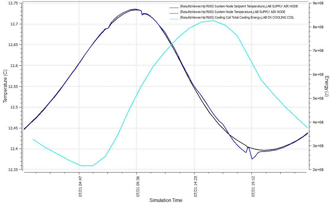
The dx cooling coil gets correctly sized. The following graph taken from one of the cooling design days shows that the supply temperature follows the supply temperature setpoint and fluctuating cooling energy.

image description

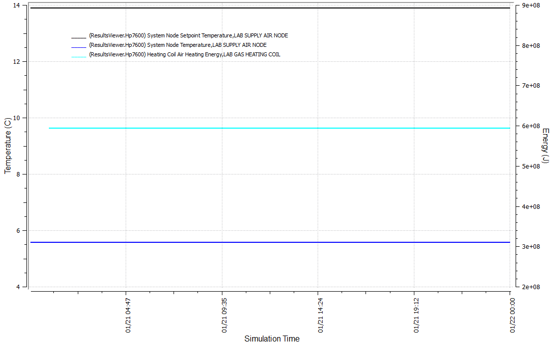
Now we look at the heating design day and see something completely different. Everything is constant and the supply air temperature is nowhere near the setpoint.

image description

I'm stumped. I can increase the Fraction of Autosized Heating Design Capacity and get it to behave, but I don't see why it's sizing the coil so much lower than what it needs for heating.

If I'm not mistaken it should be grabbing the heating flow rate from the zone terminals, then it's just a matter of btu = Q * deltaT to get the btu/h required for the coil. deltaT would be based off the OAT for the design day and the central heating temperature found in the zone sizing object. Based on the *.eio the calculated heating design flow rate is 9.55613 m3/s or 20239.88 cfm, so a quick calculation yields 20239.88 * (57 - 5.9) * 1.08 = 1,116,999 btu. This is compared to the 562,513.3 btu that is being calculated for the capacity by E+.

If I hardsize it using my calculated value, it again responds appropriately adhering to the setpoint. Maybe this is a convergence issue since it's such a high flow rate loop or is there something else I'm missing?

Sizing Object...

Sizing:System,
Lab RTU,                                !- AirLoop Name
Sensible,                               !- Type of Load to Size On
Autosize,                               !- Design Outdoor Air Flow Rate {m3/s}
0.3,                                    !- Central Heating Maximum System Air Flow Ratio
-17.7777777777777,                      !- Preheat Design Temperature {C}
0.008,                                  !- Preheat Design Humidity Ratio {kgWater/kgDryAir}
-17.7777777777777,                      !- Precool Design Temperature {C}
0.008,                                  !- Precool Design Humidity Ratio {kgWater/kgDryAir}
11.1111111111111,                       !- Central Cooling Design Supply Air Temperature {C}
13.8888888888889,                       !- Central Heating Design Supply Air Temperature {C}
NonCoincident,                          !- Type of Zone Sum to Use
Yes,                                    !- 100% Outdoor Air in Cooling
Yes,                                    !- 100% Outdoor Air in Heating
0.0085,                                 !- Central Cooling Design Supply Air Humidity Ratio {kgWater/kgDryAir}
0.008,                                  !- Central Heating Design Supply Air Humidity Ratio {kgWater/kgDryAir}
DesignDay,                              !- Cooling Supply Air Flow Rate Method
10.88,                                  !- Cooling Supply Air Flow Rate {m3/s}
0.01016,                                !- Cooling Supply Air Flow Rate Per Floor Area {m3/s-m2}
1,                                      !- Cooling Fraction of Autosized Cooling Supply Air Flow Rate
3.94754559999994e-005,                  !- Cooling Supply Air Flow Rate Per Unit Cooling Capacity {m3/s-W}
DesignDay,                              !- Heating Supply Air Flow Rate Method
10.88,                                  !- Heating Supply Air Flow Rate {m3/s}
0.01016,                                !- Heating Supply Air Flow Rate Per Floor Area {m3/s-m2}
1,                                      !- Heating Fraction of ...
(more)
edit retag flag offensive close merge delete

Comments

If you send me the input file I'll tell you how the heating coil gets sized. Email is shown on users page.

rraustad's avatar rraustad  ( 2016-08-23 15:00:20 -0500 )edit

It is right there in the Sizing:System object

0.3, !- Central Heating Maximum System Air Flow Ratio

Archmage's avatar Archmage  ( 2016-08-24 08:46:50 -0500 )edit

...awkward...That field seems extraneous and even then, why would the eio not reflect this value in the Calculated Heating Design Air Flow Rate? If I see XXXX for the heating design air flow rate, I would expect that to be the value that equipment is sized off of.

This also becomes an OS issue now since that field is labeled as Minimum System Air Flow Ratio which means something completely different than Central Heating Maximum System Air Flow Ratio. I didn't even think to check that.

Adam Hilton's avatar Adam Hilton  ( 2016-08-24 09:18:38 -0500 )edit

1 Answer

Sort by ยป oldest newest most voted
1

answered 2016-08-23 16:07:26 -0500

updated 2016-08-23 20:15:33 -0500

I'm getting a different answer than yours in V8.6. Not sure if I am doing something wrong or if something changed between V8.5 and V8.6. I did pull your weather file so that's not it.

For the Lab Gas Heating Coil I get:

DesVolFlow = 3.27593 m3/s
DesMassFlow = 3.30242 kg/s
CoilInletTemp = -14.5 C
CoilOutletTemp = 13.88888 C
CpAirStd = 1004.8586
CoilLoad = CpAirStd * DesMassFlow * ( CoilOutletTemp - CoilInletTemp )
CoilLoad = 94207.4 Watts

From the eio:

Component Sizing Information, Coil:Heating:Fuel, LAB GAS HEATING COIL, Design Size Nominal Capacity [W], 94207.40944
Component Sizing Information, Fan:VariableVolume, LAB VARIABLE VOLUME SUPPLY FAN, Design Size Maximum Flow Rate [m3/s], 10.91976

So the question is why the flow is reported as 10.9 m3/s when sizing is using 3.3 m3/s?

It might be because the terminal units use a 0.3 fraction for minimum air flow and the heating coil mistakenly uses this value.

AirTerminal:SingleDuct:VAV:Reheat,
   0.3,                                    !- Constant Minimum Air Flow Fraction
edit flag offensive delete link more

Comments

Thanks for looking at that. 3.27 m3/s is 30% of 10.92, so that would make sense, but yes, I don't see why it would be using that value as the design flow. In the eio it says System Sizing Information, LAB RTU, Calculated Heating Design Air Flow Rate [m3/s], 9.55613, and to me that would seem the logical value to size the heating coil off of. I have the terminal devices set as reverse action and the majority of the Design Size Maximum Flow Fraction during Reheat are being sized to 1 so peak heating load would never be at 30% flow.

Adam Hilton's avatar Adam Hilton  ( 2016-08-23 16:30:01 -0500 )edit

Yes, the value of 10.92 should be used, however, the logic in code is forcing use of the lower air flow. This needs to be corrected.

rraustad's avatar rraustad  ( 2016-08-23 19:16:25 -0500 )edit

Perfect, thanks for clarifying.

Adam Hilton's avatar Adam Hilton  ( 2016-08-23 20:09:05 -0500 )edit

Let me follow up on this topic. Is the only issue that the outlet temperature does not follow the set point? What I mean is, do the zone conditions suffer because of the lower heating coil capacity? If a VAV system only uses the terminal heating coil to maintain the heating set point, then why would a main heating coil need a capacity greater than what the terminal unit needs? This change would oversize the heating coil by a factor of 3.3 and I hesitate to change this if unnecessary.

rraustad's avatar rraustad  ( 2016-08-24 07:47:42 -0500 )edit

In the Sizing:System object, the Central Heating Maximum System Airflow Ratio sizes the main heating coil. Yours is set at 0.3.

IO Ref:

Central Heating Maximum System Air Flow Ratio The ratio of the maximum system air flow rate for heating to the maximum system air flow rate. This ratio should be set to reflect what the user expects the system flow rate to be when maximum heating demand occurs. This ratio is used in calculating the system heating capacity. See V8.5 Pg 670 for more text

rraustad's avatar rraustad  ( 2016-08-24 09:18:56 -0500 )edit

Your Answer

Please start posting anonymously - your entry will be published after you log in or create a new account.

Add Answer

Training Workshops

Careers

Question Tools

2 followers

Stats

Asked: 2016-08-23 13:57:03 -0500

Seen: 448 times

Last updated: Aug 23 '16