Question-and-Answer Resource for the Building Energy Modeling Community
Get started with the Help page
Ask Your Question
6

Thermal Energy Storage configuration

asked 2016-06-16 13:08:24 -0500

Matt Koch's avatar

updated 2016-06-17 06:59:07 -0500

I am trying to configure a simple chilled water loop to include a Thermal Energy Storage (TES) tank. The Plant Applications guide suggests for this to be in series with the chiller, but in the configuration I have in mind, it is in parallel with the chiller.

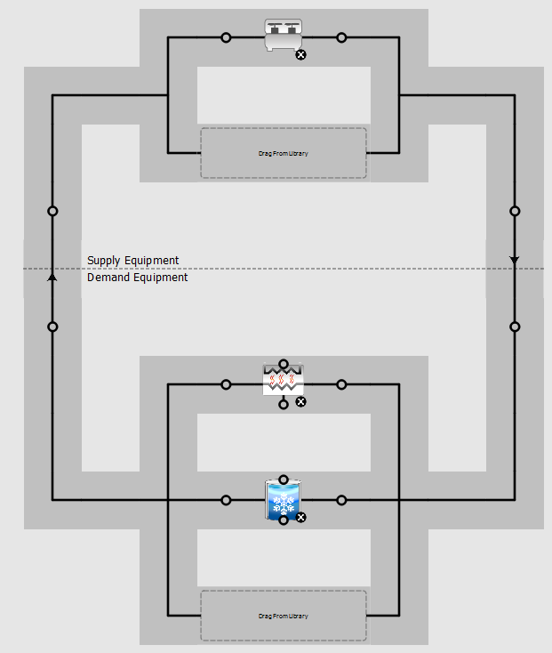
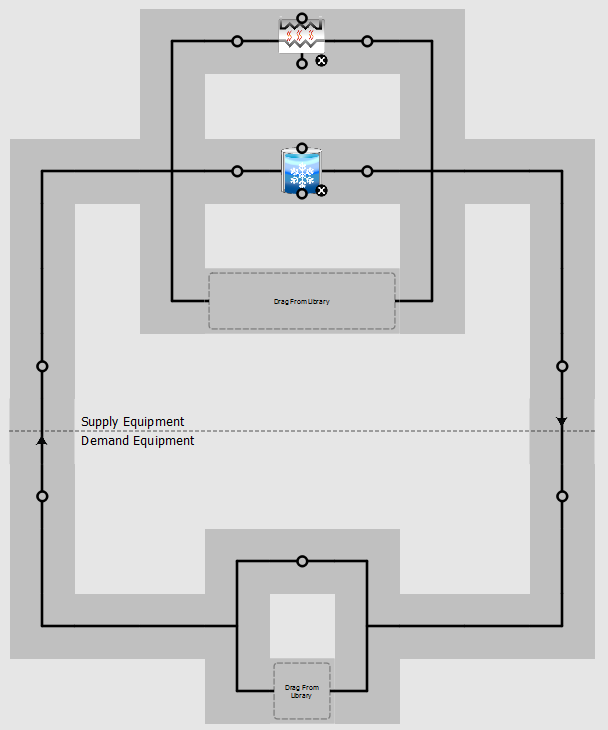
The intent is for either the chiller or the tank or both to supply chilled water to the air handlers during the day, and for the chiller to supply chilled water back to the tank during the night. So, following EnergyPlus/OpenStudio lingo, in a sense, the tank would be on the "supply" side during the day but on the "demand" side during the night?

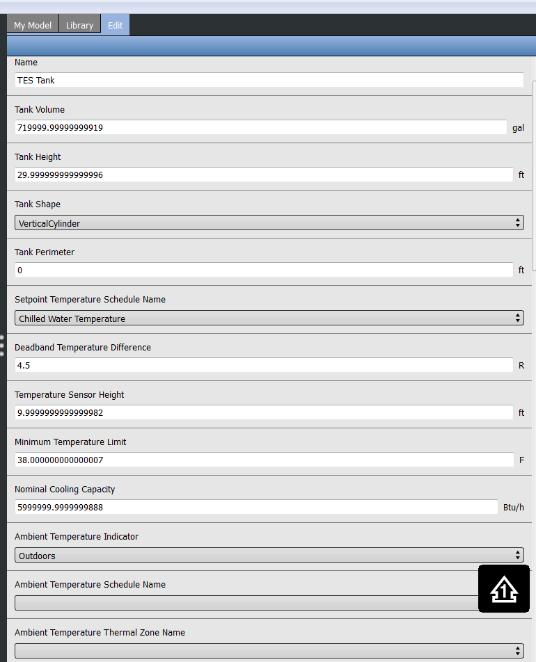
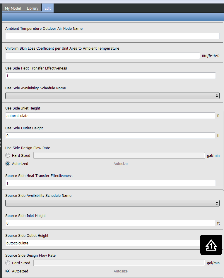
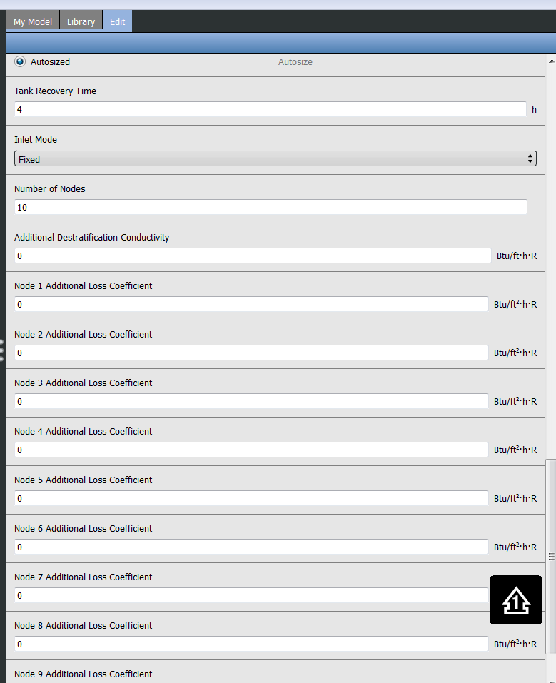
Somehow, I suspect this is related to the source and use sides of the ThermalStorage:ChilledWater:Stratified object - alas, it talks about source side inlet and outlet and use side inlet and outlet, so I would suspect there to be four nodes on this object, but there are only two?

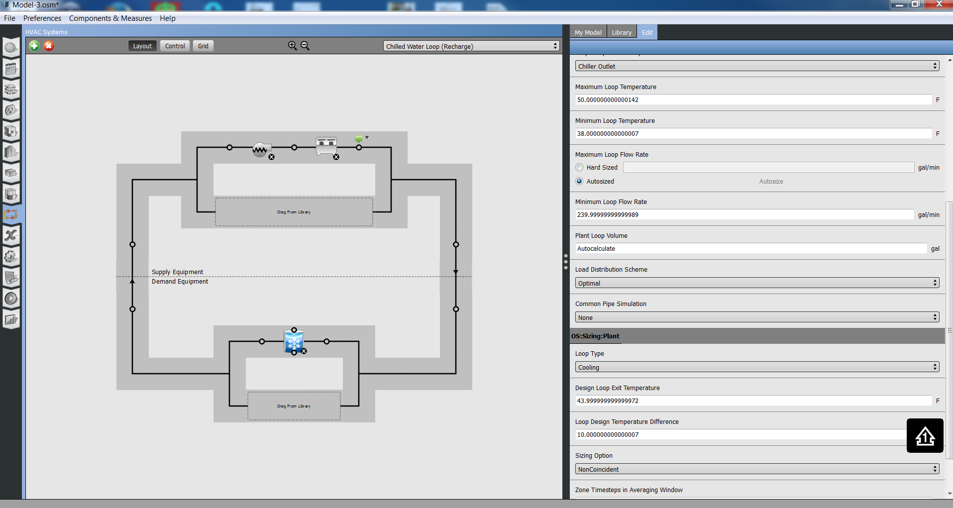
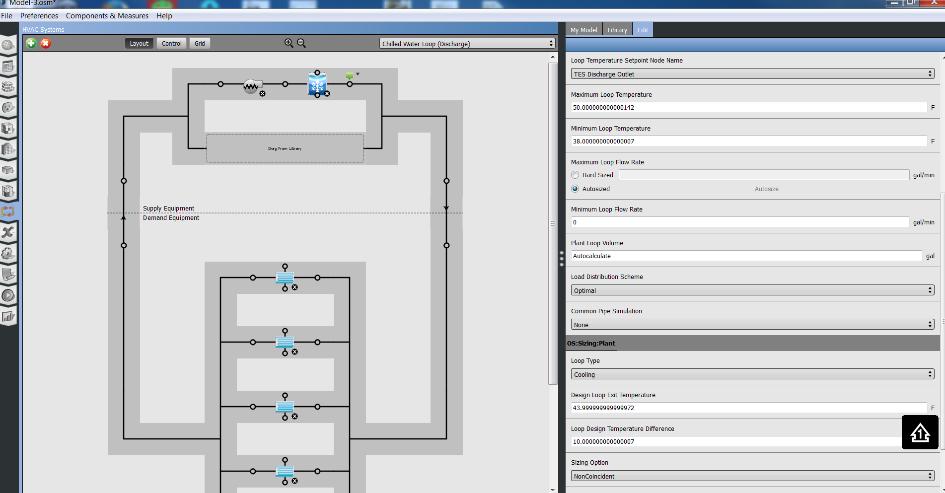
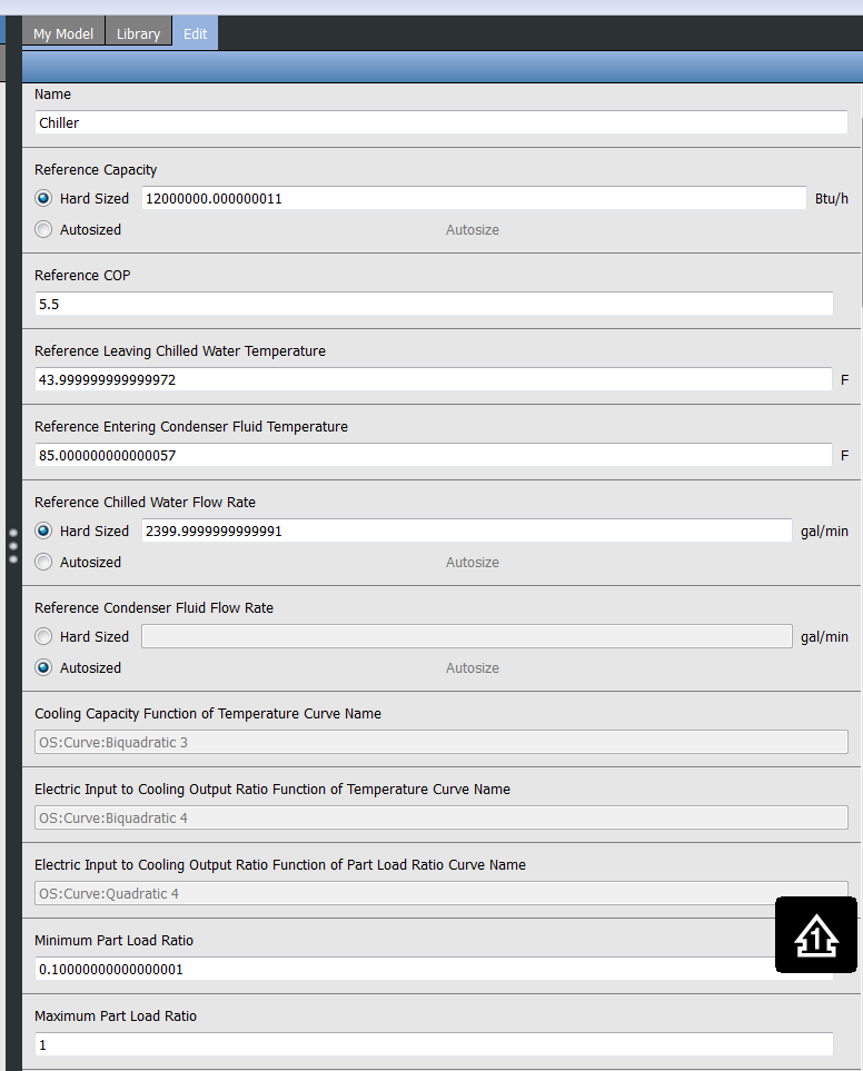
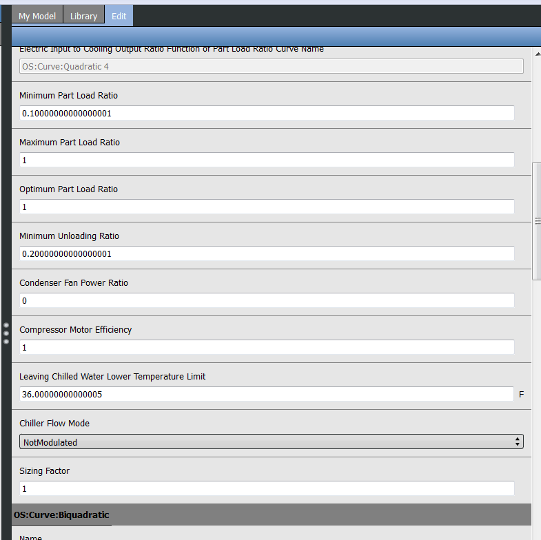
In essence then, how would I incorporate this tank on the "HVAC Systems" tab of OpenStudio - other than in series with the chiller - so as to achieve my objective above? I searched high and low but could not find any suitable screenshots online.

edit retag flag offensive close merge delete

2 Answers

Sort by ยป oldest newest most voted
2

answered 2016-06-17 06:55:35 -0500

updated 2016-06-17 06:58:39 -0500

The ThermalStorage:ChilledWater:Stratified has four nodes to be able to connect it on the source and use sides. The fact that you cannot do that in OpenStudio App seems like a bug to me. The WaterHeater objects used to have the same bug, at the time I wrote this measure that you could repurpose easily.

Here's something you can do:

  • Have a Plant loop with the chiller on the supply side, and two branches on the demand
  • Put your storage tank across the loops, and an ideal heat exchanger.

I created an example model with the following code in terminal and then adding the chiller and HX in the OS App:

model = OpenStudio::Model::Model.new
source_plant = OpenStudio::Model::PlantLoop.new(model)
use_plant = OpenStudio::Model::PlantLoop.new(model)
tank = OpenStudio::Model::ThermalStorageChilledWaterStratified.new(model)
source_plant.addDemandBranchForComponent(tank)
use_plant.addSupplyBranchForComponent(tank)

Here's the 'Chiller ChW Loop':

Chiller ChW Loo

Here's the 'Building ChW Loop'

Building ChW Loop

edit flag offensive delete link more

Comments

If you don't get why this would be equivalent to your actual piping arrangement, I suggest taking a pen an paper to draw this and your actual piping layout, and try to connect the dots.

Julien Marrec's avatar Julien Marrec  ( 2016-06-17 07:00:47 -0500 )edit

Thank you Julien. This is mighty impressive work. I think I understand how your two diagrams work together. I presume the tank's source controls would determine whether chilled water on the Chiller Loop side would enter the tank to recharge it, or would simply flow through the heat exchanger. Also, the tank's use controls would determine when chilled water on the Building Loop side can be drawn from it? Could there be simultaneous source and use action? Also, what controls would prevent chilled water from running through the heat exchanger when I want to run the building on the tank only?

Matt Koch's avatar Matt Koch  ( 2016-06-17 07:47:28 -0500 )edit

Further, by ideal heat exchanger, I presume you mean a pure counter-flow one with infinitely high overall heat transfer coefficient, so that the NTU is infinity and the effectiveness is unity, with equal flows on the hot and cold side, making not only the temperature deltas on both side the same, but also making Thotin = Tcoldout and Thoutout = Tcoldin, whereby Tcoldin is that of the chilled water from the chiller (Chiller Loop) and Thotout is that of the chilled water to the air handlers (Building Loop)?

Matt Koch's avatar Matt Koch  ( 2016-06-17 08:25:04 -0500 )edit

Actually, as I am trying to implement your suggestions, I am encountering a hurdle with your statement "...created an example model with the following code in terminal and then adding the chiller and HX in the OS ...". How do I make use of the code snippet that follows right after that sentence? I apologize, I am getting better at OS/EP, but I am still fairly new to these, and I am not a Ruby programmer, either. I also noticed that your images show the tank with four (not just two) nodes. Is that the result of your code snippet, or are you working with a newer version of OS (mine is 1.11.0)?

Matt Koch's avatar Matt Koch  ( 2016-06-17 10:57:07 -0500 )edit

Matt, I used the snippet to connect the tank on both loop because right now you can't do that in OS (likely a bug, I should open an issue on github). You can either use a terminal (see Optional - Install ruby or implement that in a measure: see a VERY similar measure I wrote here. I also updated this example here

Julien Marrec's avatar Julien Marrec  ( 2016-06-18 03:01:44 -0500 )edit
1

answered 2016-06-22 07:59:53 -0500

Matt Koch's avatar

So, I have arrived at the following configuration. The Recharge Loop is supposed to do nothing but pump warmer chilled water from the top of the TES tank and cooler chilled water back to the bottom of the TEES tank, whenever such is deemed necessary. The chiller achieves the necessary cooling, of course. The Discharge Loop is supposed to do nothing but pump cooler chilled water from the bottom of TES tank to the air handler coils and warmer chilled water back to the top of the TES tank.

Recharge Loop: image description

Discharge Loop: image description

The necessary control is supposed to be achieved through the TES tank dead band temperature. As I understand it, if the temperature at the sensor location (here 10 ft up in a 30 ft TES tank) exceeds the set point temperature (here 44 oF) by the dead band (here 4.5 oF), i.e. reaches 48.5 oF, then the chiller is commanded to come on and chill the TES tank back down via the Recharge Loop.

Speaking of chiller, here are the chiller parameters:

image description image description

And speaking of TES tank, here are the TES tank parameters:

image description image description image description

What I observe thus far (by using the OpenStudio Node Diagnostics measure at the two chiller nodes and four TES tank nodes) is not clearly demonstrating to me that this does or does not work. I believe I sized the TES tank and chiller such that the chiller ought to be able to be off for extended periods at a time and just let the TES tank carry the load, yet it seems that the chiller is consuming massive amounts of power most of the day. The two (green) set point managers you see in the above images both reference the CHW set-point schedule (constant 44 oF), by the way.

Not sure if this gets too far into the weeds and is inappropriate for this website, but if not, and if you have any insight here, I would certainly much appreciate such. I believe I am missing something that may be obvious to someone who has been through this before?

Tanks,

Matt Koch

edit flag offensive delete link more

Comments

Not really an answer is it? =)

Julien Marrec's avatar Julien Marrec  ( 2016-06-22 10:02:29 -0500 )edit

Well, how about a partial or alternative answer - to build upon by people much smarter than I am? It could well be that this works the way it is supposed to per OpenStudio, I just can't tell for sure.

Matt Koch's avatar Matt Koch  ( 2016-06-22 10:37:53 -0500 )edit

As I keep exploring this, it appears to me that the chilled water loop recharge the TES tank should probably operate at a temperature lower than that of the chilled water discharge loop. Also, perhaps the chilled water recharge loop might need a bypass to the TES tank, so that the minimum flow through the chiller can be maintained even when the TES tank is not calling for recharge.

Matt Koch's avatar Matt Koch  ( 2016-06-23 07:58:13 -0500 )edit

You already have a bypass on the supply and on the demand side, even if you don't know it. Look a the resulting IDF to confirm

Julien Marrec's avatar Julien Marrec  ( 2016-06-23 09:02:30 -0500 )edit

How can you connect the storage into the loop ? It didn't show up in My Model section. Only found in the library, so I can't connect it to the chiller.

BL's avatar BL  ( 2016-11-17 09:57:50 -0500 )edit

Your Answer

Please start posting anonymously - your entry will be published after you log in or create a new account.

Add Answer

Careers

Question Tools

2 followers

Stats

Asked: 2016-06-16 13:08:24 -0500

Seen: 838 times

Last updated: Jun 22 '16