Question-and-Answer Resource for the Building Energy Modeling Community
Get started with the Help page
Ask Your Question
1

design size rated cooling vs calculated design load

asked 2016-06-07 13:47:46 -0600

HJOJOA's avatar

updated 2016-10-18 14:08:17 -0600

Hi,

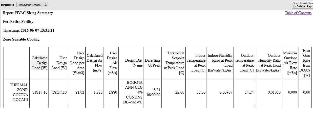
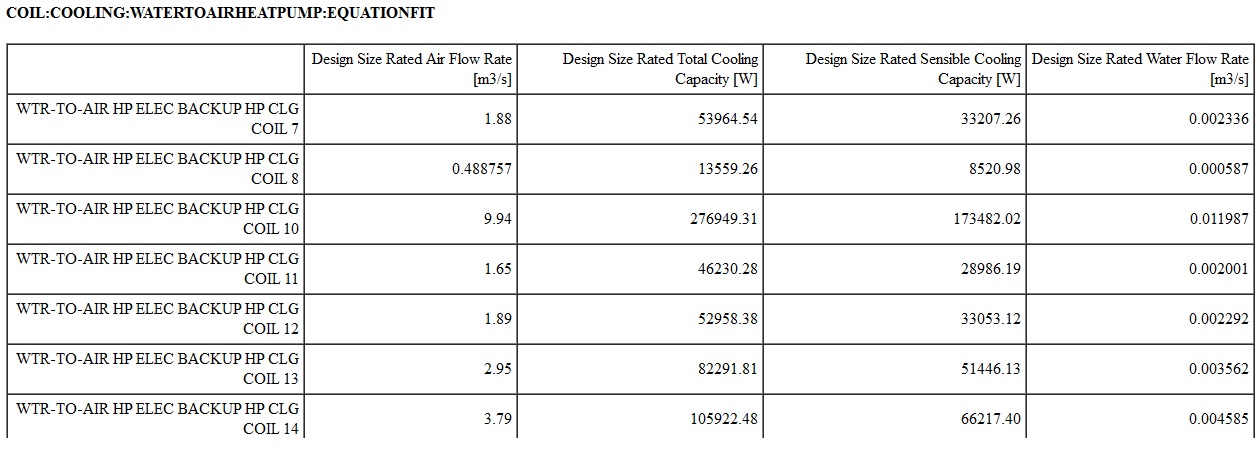
In a project, a thermal zone with a doa and a default water to air heat pump, cooling thermostat 22°C, the maximum outdoor temp is 21°C, and density correction fctor is 0.731, the resultant are:

Design Size Rated Total Cooling Capacity 53964 W image description (the first)

CALCULATED DESIGN LOAD 18,117 W image description

If the there is no heat gain from DOA, why is the difference between results?

There is no safety factor in the project.

How can i attach a project?

edit retag flag offensive close merge delete

Comments

Please tag with software you are using. Also, please try to avoid creating new tags. Nobody is subscribed to the tag 'vs'. Thanks.

__AmirRoth__'s avatar __AmirRoth__  ( 2016-06-07 14:13:16 -0600 )edit

OPEN STUDIO 1.10.0, because this version allow me to select air cooled chillers with evaporative condenser and the latest version doesn't allow this.

HJOJOA's avatar HJOJOA  ( 2016-06-07 14:39:38 -0600 )edit

can you please retag?

__AmirRoth__'s avatar __AmirRoth__  ( 2016-06-07 15:00:28 -0600 )edit

1 Answer

Sort by » oldest newest most voted
1

answered 2016-06-07 14:24:05 -0600

updated 2016-06-07 14:55:00 -0600

You could try turning off the DOA and try this again. I have found that when DOA is used, the entering humidity ratio used for sizing the cooling coil is higher than it should be since the "zone" does have outdoor air supplied to the space even thought it is not through the cooling coil. Note the indoor humidity ratio shown above = 0.009 when the outdoor humidity ratio = 0.01. A zone with DOA should have a lower humidity ratio than shown here. For example, 22C DBT/50% RH = 0.008. The higher zone humidity ratio causes a larger cooling coil size.

The other input that affects coil size is the total cooling capacity coefficients which are used during sizing. Coil:Cooling:WaterToAirHeatPump:EquationFit, N6, \field Total Cooling Capacity Coefficient 1 N7, \field Total Cooling Capacity Coefficient 2 N8, \field Total Cooling Capacity Coefficient 3 N9, \field Total Cooling Capacity Coefficient 4 N10, \field Total Cooling Capacity Coefficient 5

Calculate the correction factor yourself to see if these inputs have an impact on coil sizing:

ratioTWB = ( MixWetBulb + 273.15 ) / 283.15;
ratioTS = ( ( ( 85.0 - 32.0 ) / 1.8 ) + 273.15 ) / 283.15;
TotCapTempModFac = TotalCapCoeff1 + ( ratioTWB * TotalCapCoeff2 ) + ( ratioTS * TotalCapCoeff3 ) + ( 1.0 * TotalCapCoeff4 ) + ( 1.0 * TotalCapCoeff5 );
CoolCapAtPeak = rhoair * VolFlowRate * ( MixEnth - SupEnth );
RatedCapCoolTotalDes = CoolCapAtPeak / TotCapTempModFac;
edit flag offensive delete link more

Comments

Is there a way to see the psycrometric calculation for the resultant? In the other hand, where can i fin this coefficient for water to air heath pump or any reference? the manufacturer catalog only show performance data, i tried to use the excel coefficient calculation included in energyplus and the resultant was out of range.

I Turned of the DOA and the result was the same, because the outdoor condition is better than indoor condition, notice the lower outdoor drybulb temp at peak condition.

HJOJOA's avatar HJOJOA  ( 2016-06-07 14:34:30 -0600 )edit

The coefficients are created from manufacturers performance data. These are a curve fit of the performance data over a range of operating conditions.

rraustad's avatar rraustad  ( 2016-06-07 15:04:53 -0600 )edit

See this doc for an example of how to do this in excel for VRF systems on page 10 and 11.

rraustad's avatar rraustad  ( 2016-06-07 15:07:07 -0600 )edit

All you would need to do is change the equation to match the TotCapTempModFac equation above. And each column represents the term in this equation (I see 4 above since the a0 term [or TotalCapCoeff1] isn't used).

ratioTDB = ( ( LoadDBT + 273.15 ) / 283.15 );
ratioTWB = ( ( LoadWBT + 273.15  ) / Tref );
ratioTS = ( ( SourceInletTemp + 273.15  ) / Tref );
ratioVL = ( LoadMassFlowRate / ( AirVolFlowRateRated * PsyRhoAirFnPbTdbW( StdBaroPress, LoadSideInletDBTemp, LoadSideInletHumRat ) ) )
rraustad's avatar rraustad  ( 2016-06-07 15:07:41 -0600 )edit

The five columns in your spreadsheet would represent these variables. You would regress the last 4 versus the first to get your 5 coefficients.

    (QLoad / TotalCapRated),  ratioTWB,  ratioTS,  ratioVL,  ratioVS
rraustad's avatar rraustad  ( 2016-06-07 15:10:18 -0600 )edit

Your Answer

Please start posting anonymously - your entry will be published after you log in or create a new account.

Add Answer

Training Workshops

Careers

Question Tools

1 follower

Stats

Asked: 2016-06-07 13:47:46 -0600

Seen: 362 times

Last updated: Jun 07 '16