You could try turning off the DOA and try this again. I have found that when DOA is used, the entering humidity ratio used for sizing the cooling coil is higher than it should be since the "zone" does have outdoor air supplied to the space even thought it is not through the cooling coil. Note the indoor humidity ratio shown above = 0.009 when the outdoor humidity ratio = 0.01. A zone with DOA should have a lower humidity ratio than shown here. For example, 22C DBT/50% RH = 0.008. The higher zone humidity ratio causes a larger cooling coil size.
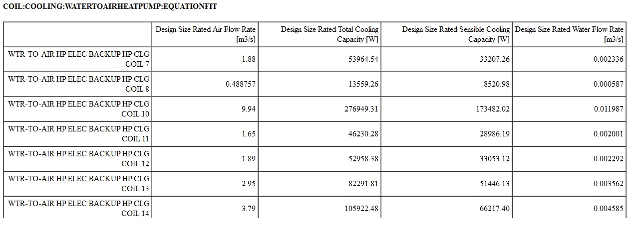
The other input that affects coil size is the total cooling capacity coefficients which are used during sizing.
Coil:Cooling:WaterToAirHeatPump:EquationFit,
N6, \field Total Cooling Capacity Coefficient 1
N7, \field Total Cooling Capacity Coefficient 2
N8, \field Total Cooling Capacity Coefficient 3
N9, \field Total Cooling Capacity Coefficient 4
N10, \field Total Cooling Capacity Coefficient 5
Calculate the correction factor yourself to see if these inputs have an impact on coil sizing:
ratioTWB = ( MixWetBulb + 273.15 ) / 283.15;
ratioTS = ( ( ( 85.0 - 32.0 ) / 1.8 ) + 273.15 ) / 283.15;
TotCapTempModFac = TotalCapCoeff1 + ( ratioTWB * TotalCapCoeff2 ) + ( ratioTS * TotalCapCoeff3 ) + ( 1.0 * TotalCapCoeff4 ) + ( 1.0 * TotalCapCoeff5 );
CoolCapAtPeak = rhoair * VolFlowRate * ( MixEnth - SupEnth );
RatedCapCoolTotalDes = CoolCapAtPeak / TotCapTempModFac;


 (the first)
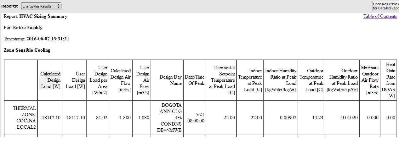


Please tag with software you are using. Also, please try to avoid creating new tags. Nobody is subscribed to the tag 'vs'. Thanks.
OPEN STUDIO 1.10.0, because this version allow me to select air cooled chillers with evaporative condenser and the latest version doesn't allow this.
can you please retag?