Question-and-Answer Resource for the Building Energy Modeling Community
| | 1 | initial version |
As long as I know, EnergyPlus cannot model DHW recirculation loop, but there is a workaround.
Let me take the ExampleFile WaterHeaterDHWPlantLoop.idf to explain. The schematic is as shown below.
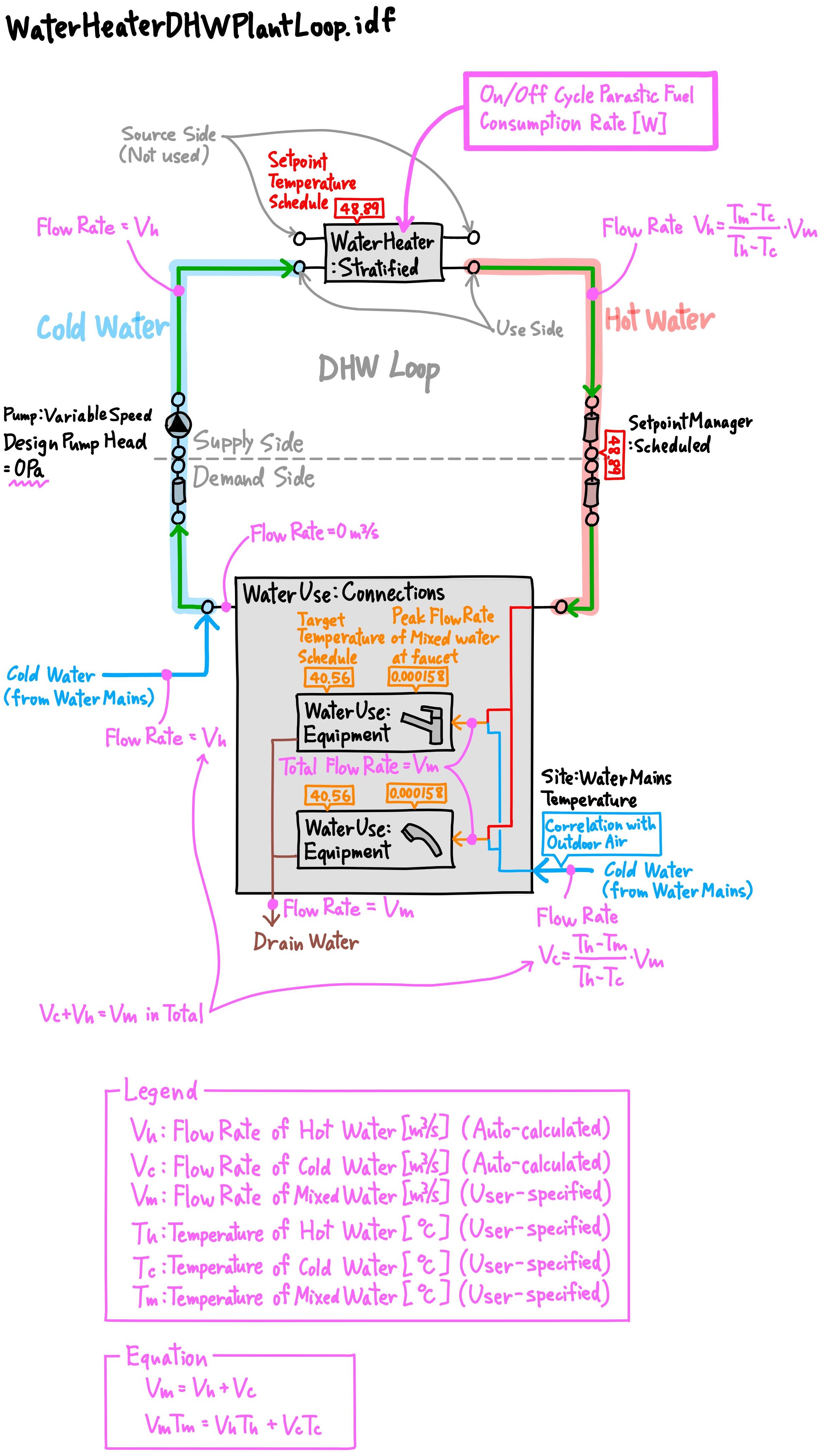
The schematic looks like a Loop at a glance, but actually, DHW is not recirculated.
The water flow rate in the DHW Loop is equal to the flow rate of hot water (Vh) which is actually consumed at water fixtures (WaterUse:Equipment).
In my MEP experience, DHW recirculation pump is to maintain the water temperature in the DHW recirculation pipe, and it is constant speed. The pump flow rate is different from the actual hot water demand which changes from time to time. However, EnergyPlus cannot model the constant-flow recirculation pump.
Design Pump Head in the ExampleFile is set to 0Pa, which indicates the pump is a "virtual" pump which is only used to drive water flow.
I think you should keep the Design Pump Head 0Pa, and the workaround to model a DHW recirculation pump is that you can add the pump power [W] of the recirculation pump (you can hand-calculate it as it should be constant) to On Cycle Parastic Fuel Consumption Rate [W] and/or Off Cycle Parastic Fuel Consumption Rate [W] in WaterHeater:Stratified or WaterHeater:Mixed. On/Off Cycle Parastic Fuel Type should be Electricity. On/Off Cycle Parastic Heat Fraction to Tank should be 1 if you want to account for the water temperature rise by the pump heat.

