Question-and-Answer Resource for the Building Energy Modeling Community
First time here? Check out the Help page!
| | 1 | initial version |
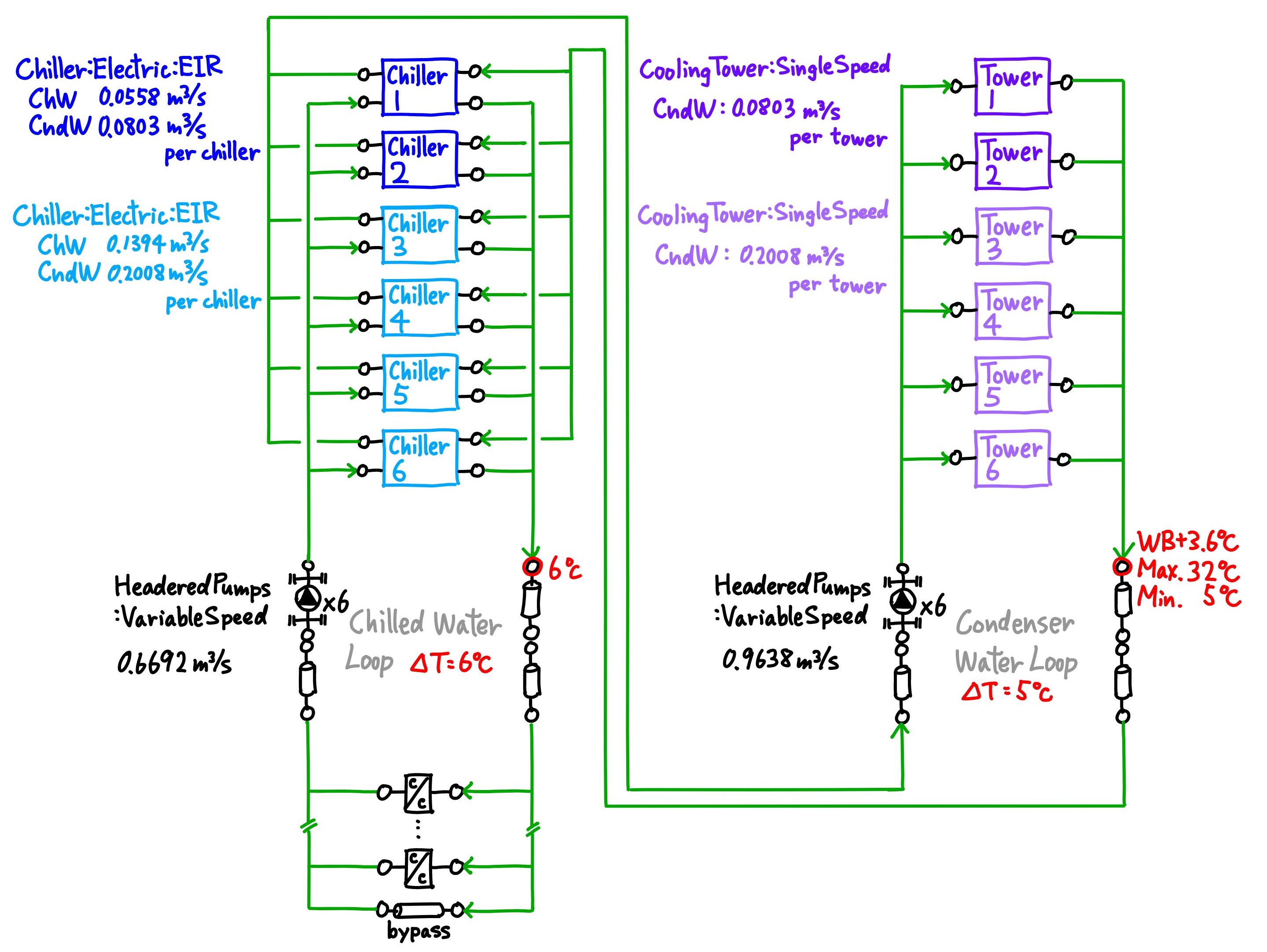
Surprisingly, EnergyPlus still lacks a feature of variable condenser water flow feature as of V23-2-0. I referred to @Julien Marrec and @Gio 's 4 year old answers.
My case is as follows. The condenser water loop has 6 nos. of CoolingTower:SingleSpeed and one HeaderedPumps:VariableSpeed with 6 pumps in bank.
After much consideration, my EMS was finally as follows.
SetpointManager:FollowOutdoorAirTemperature,
    CHWloop CndW Temp Manager,  !- Name
    Temperature,             !- Control Variable
    OutdoorAirWetBulb,       !- Reference Temperature Type
    3.6,                     !- Offset Temperature Difference {deltaC}
    32,                      !- Maximum Setpoint Temperature {C}
    5,                       !- Minimum Setpoint Temperature {C}
    CHWloop CndW Supply Setpoint Nodes;  !- Setpoint Node or NodeList Name

EnergyManagementSystem:Sensor,
    ChW_Supply_Cooling_Demand,  !- Name
    CHWloop Chilled Water Loop,  !- Output:Variable or Output:Meter Index Key Name
    Plant Supply Side Cooling Demand Rate;  !- Output:Variable or Output:Meter Name

EnergyManagementSystem:Sensor,
    CndW_Supply_Inlet_Temp,  !- Name
    CHWloop Condenser Water Loop,  !- Output:Variable or Output:Meter Index Key Name
    Plant Supply Side Inlet Temperature ;  !- Output:Variable or Output:Meter Name

EnergyManagementSystem:Sensor,
    Site_OA_WB,              !- Name
    Environment,             !- Output:Variable or Output:Meter Index Key Name
    Site Outdoor Air Wetbulb Temperature ;  !- Output:Variable or Output:Meter Name

EnergyManagementSystem:Actuator,
    CndW_Supply_Pump_Mass_Flow,  !- Name
    CndW Supply Pump,!- Actuated Component Unique Name
    Pump,                    !- Actuated Component Type
    Pump Mass Flow Rate;     !- Actuated Component Control Type

EnergyManagementSystem:ProgramCallingManager,
    EMS_PCM_CndW_Supply_Pump_Mass_Flow_Override,  !- Name
    InsideHVACSystemIterationLoop,  !- EnergyPlus Model Calling Point
    EMS_Program_CndW_Supply_Pump_Mass_Flow_Override;  !- Program Name 1

EnergyManagementSystem:Program,
    EMS_Program_CndW_Supply_Pump_Mass_Flow_Override,  !- Name
    IF ChW_Supply_Cooling_Demand == 0,  !- Program Line 1
    SET CndW_Supply_Pump_Mass_Flow = 0,  !- Program Line 2
    ELSEIF CndW_Supply_Inlet_Temp <= 5,  !- A4
    SET CndW_Supply_Pump_Mass_Flow = 80.3,  !- A5
    ELSEIF Site_OA_WB <= 1.4,  !- A6
    SET CndW_Supply_Pump_Mass_Flow = @MIN 963.8 (ChW_Supply_Cooling_Demand * 1.25 / 4180 / (CndW_Supply_Inlet_Temp - 5)),  !- A7
    ELSE,                    !- A8
    SET CndW_Supply_Pump_Mass_Flow = @MIN 963.8 (ChW_Supply_Cooling_Demand * 1.25 / 4180 / (CndW_Supply_Inlet_Temp - (Site_OA_WB + 3.6))),  !- A9
    ENDIF;                   !-
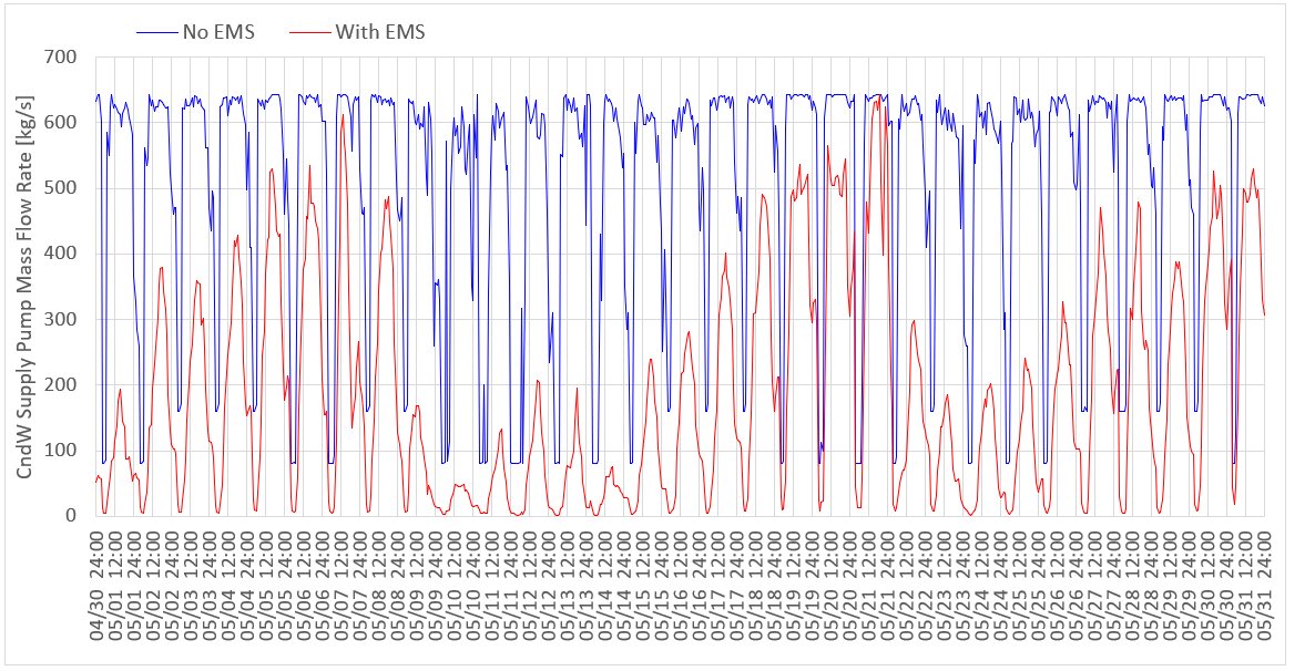
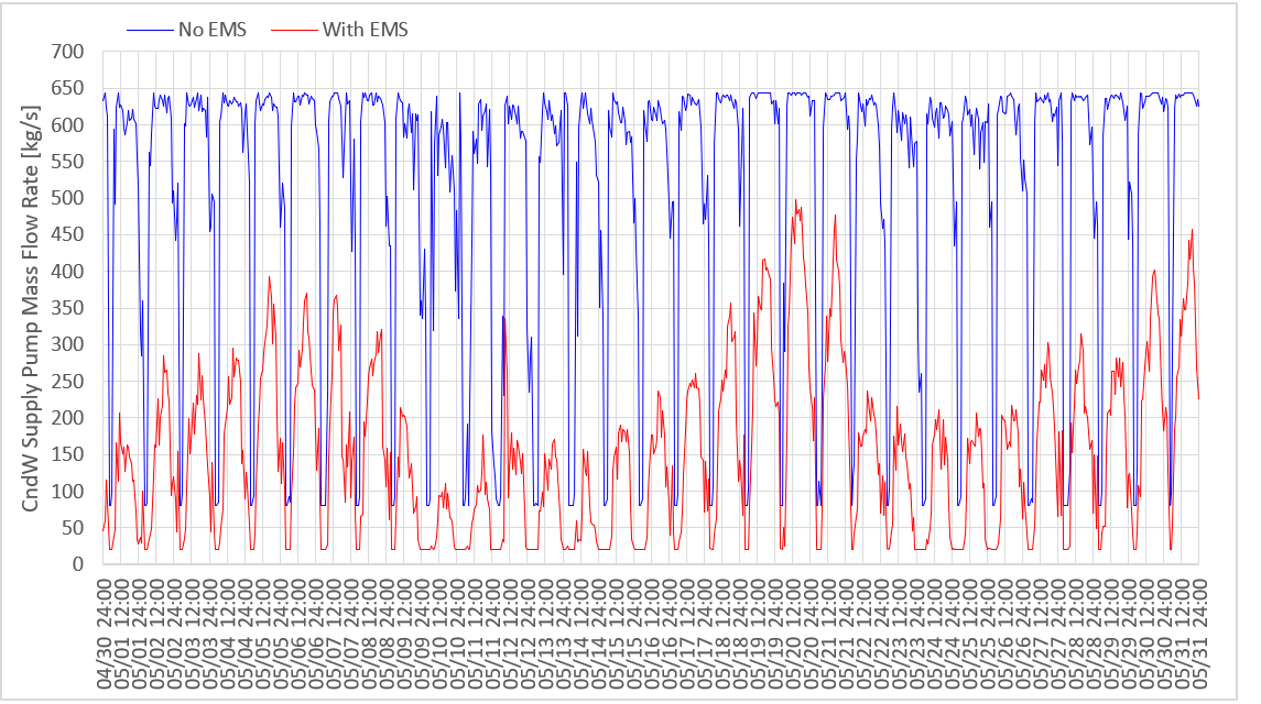
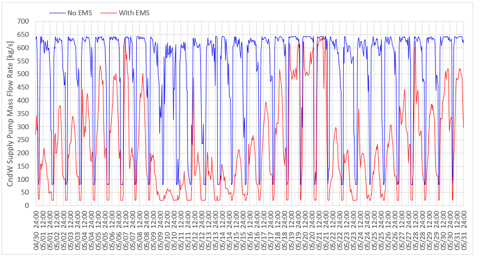
The chart below shows the condensor water pump flow rate of two cases (No EMS and With EMS) in May as an example. The building has retails, restaurants and plant rooms, and chillers run 24h/day. Please note that since the condenser water pump is a headered pump with 6 pumps in bank, the condenser water flow rate varies to some extent according to the number of cooling towers in operation even if there is no EMS. HeaderedPumps:VariableSpeed acts as if it is HeaderedPumps:ConstantSpeed if there is no EMS.
The annual electricity end uses are -56.5% condenser water pump, +5.7% heat rejection, -1.3% cooling, and -0.3% chilled water pump. The total end use of above 4 categories is -12.7%.
Here are some findings.
I had to use Plant Supply Side Cooling Demand Rate [W] of Chilled water loop instead of Condenser water loop to calculate Pump Mass Flow Rate of the condenser water pump. When I used Plant Supply Side Cooling Demand Rate [W] of Condenser water loop, it became zero and Pump Mass Flow Rate of the condenser water pump became zero as well. The simulation did not terminate, but I got thousands of unmet hours as the cooling load was not handled. I could not identify the cause, but there may be something wrong during warmup. When I used Plant Supply Side Cooling Demand Rate [W] of Chilled water loop, I multiplied 1.25, which is shown in the lines A7 and A9 of EnergyManagementSystem:Program. It is because Output:variables showed that Condenser water cooling demand rate is around 25% larger than Chilled water cooling demand rate on average, which is aligned with this discription in I/O Reference.
The equation of mass flow rate that Julien showed cannot be used as it is. The simulation starts with the minimum water temperature for both inlet and outlet i.e., TEWT = TLWT. The denominator of the equation becomes zero at the start of the simulation. I got the following severe error and the simulation terminated.
I wanted to avoid the severe error above, but I needed to drive the condenser water pump at the start of the simulation. So, I have set the constant condenser water pump flow rate (80.3kg/s which is equal to the smallest pump of 6 pumps in bank) when the condenser water loop supply inlet temperature is 5ºC which is the Minimum Loop Temperature of CondenserLoop in my case. The code is shown in the line A4 and A5 of EnergyManagementSystem:Program.
**  ~~~   ** Error message:  *** Error: EvaluateExpression: Divide By Zero in EMS Program! ***
**  ~~~   **  During Warmup, Environment=CHICAGO ANN HTG 99.6% CONDNS DB HVAC Sizing Pass 1, at Simulation time=01/21 00:00 - 00:01
** Fatal  ** Previous EMS error caused program termination.
After I solved the severe error at the start of the simulation, I got another severe error of "Plant temperatures are getting far too hot" and the simulation terminated again. In conlusion, I solved the error by using "Outdoor air wet-bulb temperature + 3.6ºC" instead of Condenser water supply side outlet temperature, which is shown in the line A9 of EnergyManagementSystem:Program. 3.6ºC is the Approach of cooling towers in my case which is set in SetpointManager:FollowOutdoorAirTemperature. The lines A6 an A7 of EnergyManagementSystem:Program is to ensure that the condenser water temperature does not fall below the minimum temperature (5ºC). Using @MIN is to ensure that the condenser pump water flow rate does not exceed the pump design flow rate (963.8kg/s). These codes may not be necessary.
** Severe  ** Plant temperatures are getting far too hot, check controls and relative loads and capacities
**   ~~~   **  During Warmup, Environment=WUHAN ANN HTG 99.6% CONDNS DB HVAC Sizing Pass 1, at Simulation time=01/21 07:15 - 07:30
**   ~~~   ** PlantLoop Name (Demand Side) = CHWLOOP CONDENSER WATER LOOP
**   ~~~   ** PlantLoop Setpoint Temperature=5.0 {C}
**   ~~~   ** PlantLoop Inlet Node (LoopSideLocation::Supply) does not have a Setpoint.
**   ~~~   ** PlantLoop Inlet Node (LoopSideLocation::Demand) does not have a Setpoint.
**   ~~~   ** PlantLoop Outlet Node (LoopSideLocation::Supply) has a Setpoint.
**   ~~~   ** PlantLoop Outlet Node (LoopSideLocation::Demand) does not have a Setpoint.
**   ~~~   ** PlantLoop Outlet Node (DemandSide) "CHWLOOP CNDW DEMAND OUTLET" has temperature=322.2 {C}
**   ~~~   ** PlantLoop Inlet Node (DemandSide) "CHWLOOP CNDW DEMAND INLET" has temperature=4.4 {C}
**   ~~~   ** PlantLoop Minimum Temperature=5.0 {C}
**   ~~~   ** PlantLoop Maximum Temperature=80.0 {C}
**   ~~~   ** PlantLoop Flow Request (LoopSideLocation::Supply)=0.0 {kg/s}
**   ~~~   ** PlantLoop Flow Request (LoopSideLocation::Demand)=959.7 {kg/s}
**   ~~~   ** PlantLoop Node (DemandSide) "CHWLOOP CNDW DEMAND OUTLET" has mass flow rate =4.4E-002 {kg/s}
This new feature requsest of variable condenser water flow rate has been abandoned for a long time. Hope it will be added to EnergyPlus soon.
| | 2 | No.2 Revision |
Surprisingly, EnergyPlus still lacks a feature of variable condenser water flow feature as of V23-2-0. I referred to @Julien Marrec and @Gio 's 4 year old answers.
My case is as follows. The condenser water loop has 6 nos. of CoolingTower:SingleSpeed and one HeaderedPumps:VariableSpeed with 6 pumps in bank.
After much consideration, my EMS was finally as follows.
SetpointManager:FollowOutdoorAirTemperature,
    CHWloop CndW Temp Manager,  !- Name
    Temperature,             !- Control Variable
    OutdoorAirWetBulb,       !- Reference Temperature Type
    3.6,                     !- Offset Temperature Difference {deltaC}
    32,                      !- Maximum Setpoint Temperature {C}
    5,                       !- Minimum Setpoint Temperature {C}
    CHWloop CndW Supply Setpoint Nodes;  !- Setpoint Node or NodeList Name

EnergyManagementSystem:Sensor,
    ChW_Supply_Cooling_Demand,  !- Name
    CHWloop Chilled Water Loop,  !- Output:Variable or Output:Meter Index Key Name
    Plant Supply Side Cooling Demand Rate;  !- Output:Variable or Output:Meter Name

EnergyManagementSystem:Sensor,
    CndW_Supply_Inlet_Temp,  !- Name
    CHWloop Condenser Water Loop,  !- Output:Variable or Output:Meter Index Key Name
    Plant Supply Side Inlet Temperature ;  !- Output:Variable or Output:Meter Name

EnergyManagementSystem:Sensor,
    Site_OA_WB,              !- Name
    Environment,             !- Output:Variable or Output:Meter Index Key Name
    Site Outdoor Air Wetbulb Temperature ;  !- Output:Variable or Output:Meter Name

EnergyManagementSystem:Actuator,
    CndW_Supply_Pump_Mass_Flow,  !- Name
    CndW Supply Pump,!- Actuated Component Unique Name
    Pump,                    !- Actuated Component Type
    Pump Mass Flow Rate;     !- Actuated Component Control Type

EnergyManagementSystem:ProgramCallingManager,
    EMS_PCM_CndW_Supply_Pump_Mass_Flow_Override,  !- Name
    InsideHVACSystemIterationLoop,  !- EnergyPlus Model Calling Point
    EMS_Program_CndW_Supply_Pump_Mass_Flow_Override;  !- Program Name 1

EnergyManagementSystem:Program,
    EMS_Program_CndW_Supply_Pump_Mass_Flow_Override,  !- Name
    IF ChW_Supply_Cooling_Demand == 0,  !- Program Line 1
    SET CndW_Supply_Pump_Mass_Flow = 0,  !- Program Line 2
    ELSEIF CndW_Supply_Inlet_Temp <= 5,  !- A4
    SET CndW_Supply_Pump_Mass_Flow = 80.3,  !- A5
    ELSEIF Site_OA_WB <= 1.4,  !- A6
    SET CndW_Supply_Pump_Mass_Flow = @MIN 963.8 (ChW_Supply_Cooling_Demand * 1.25 / 4180 / (CndW_Supply_Inlet_Temp - 5)),  !- A7
    ELSE,                    !- A8
    SET CndW_Supply_Pump_Mass_Flow = @MIN 963.8 (ChW_Supply_Cooling_Demand * 1.25 / 4180 / (CndW_Supply_Inlet_Temp - (Site_OA_WB + 3.6))),  !- A9
    ENDIF;                   !-
!- A10
The chart below shows the condensor water pump flow rate of two cases (No EMS and With EMS) in May as an example. The building has retails, restaurants and plant rooms, and chillers run 24h/day. Please note that since the condenser water pump is a headered pump with 6 pumps in bank, the condenser water flow rate varies to some extent according to the number of cooling towers in operation even if there is no EMS. HeaderedPumps:VariableSpeed acts as if it is HeaderedPumps:ConstantSpeed if there is no EMS.
The annual electricity end uses are -56.5% condenser water pump, +5.7% heat rejection, -1.3% cooling, and -0.3% chilled water pump. The total end use of above 4 categories is -12.7%.
Here are some findings.
I had to use Plant Supply Side Cooling Demand Rate [W] of Chilled water loop instead of Condenser water loop to calculate Pump Mass Flow Rate of the condenser water pump. When I used Plant Supply Side Cooling Demand Rate [W] of Condenser water loop, it became zero and Pump Mass Flow Rate of the condenser water pump became zero as well. The simulation did not terminate, but I got thousands of unmet hours as the cooling load was not handled. I could not identify the cause, but there may be something wrong during warmup. When I used Plant Supply Side Cooling Demand Rate [W] of Chilled water loop, I multiplied 1.25, which is shown in the lines A7 and A9 of EnergyManagementSystem:Program. It is because Output:variables showed that Condenser water cooling demand rate is around 25% larger than Chilled water cooling demand rate on average, which is aligned with this discription in I/O Reference.
The equation of mass flow rate that Julien showed cannot be used as it is. The simulation starts with the minimum water temperature for both inlet and outlet i.e., TEWT = TLWT. The denominator of the equation becomes zero at the start of the simulation. I got the following severe error and the simulation terminated.
I wanted to avoid the severe error above, but I needed to drive the condenser water pump at the start of the simulation. So, I have set the constant condenser water pump flow rate (80.3kg/s which is equal to the smallest pump of 6 pumps in bank) when the condenser water loop supply inlet temperature is 5ºC which is the Minimum Loop Temperature of CondenserLoop in my case. The code is shown in the line A4 and A5 of EnergyManagementSystem:Program.
**  ~~~   ** Error message:  *** Error: EvaluateExpression: Divide By Zero in EMS Program! ***
**  ~~~   **  During Warmup, Environment=CHICAGO ANN HTG 99.6% CONDNS DB HVAC Sizing Pass 1, at Simulation time=01/21 00:00 - 00:01
** Fatal  ** Previous EMS error caused program termination.
After I solved the severe error at the start of the simulation, I got another severe error of "Plant temperatures are getting far too hot" and the simulation terminated again. In conlusion, I solved the error by using "Outdoor air wet-bulb temperature + 3.6ºC" instead of Condenser water supply side outlet temperature, which is shown in the line A9 of EnergyManagementSystem:Program. 3.6ºC is the Approach of cooling towers in my case which is set in SetpointManager:FollowOutdoorAirTemperature. The lines A6 an A7 of EnergyManagementSystem:Program is to ensure that the condenser water temperature does not fall below the minimum temperature (5ºC). Using @MIN is to ensure that the condenser pump water flow rate does not exceed the pump design flow rate (963.8kg/s). These codes may not be necessary.
** Severe  ** Plant temperatures are getting far too hot, check controls and relative loads and capacities
**   ~~~   **  During Warmup, Environment=WUHAN ANN HTG 99.6% CONDNS DB HVAC Sizing Pass 1, at Simulation time=01/21 07:15 - 07:30
**   ~~~   ** PlantLoop Name (Demand Side) = CHWLOOP CONDENSER WATER LOOP
**   ~~~   ** PlantLoop Setpoint Temperature=5.0 {C}
**   ~~~   ** PlantLoop Inlet Node (LoopSideLocation::Supply) does not have a Setpoint.
**   ~~~   ** PlantLoop Inlet Node (LoopSideLocation::Demand) does not have a Setpoint.
**   ~~~   ** PlantLoop Outlet Node (LoopSideLocation::Supply) has a Setpoint.
**   ~~~   ** PlantLoop Outlet Node (LoopSideLocation::Demand) does not have a Setpoint.
**   ~~~   ** PlantLoop Outlet Node (DemandSide) "CHWLOOP CNDW DEMAND OUTLET" has temperature=322.2 {C}
**   ~~~   ** PlantLoop Inlet Node (DemandSide) "CHWLOOP CNDW DEMAND INLET" has temperature=4.4 {C}
**   ~~~   ** PlantLoop Minimum Temperature=5.0 {C}
**   ~~~   ** PlantLoop Maximum Temperature=80.0 {C}
**   ~~~   ** PlantLoop Flow Request (LoopSideLocation::Supply)=0.0 {kg/s}
**   ~~~   ** PlantLoop Flow Request (LoopSideLocation::Demand)=959.7 {kg/s}
**   ~~~   ** PlantLoop Node (DemandSide) "CHWLOOP CNDW DEMAND OUTLET" has mass flow rate =4.4E-002 {kg/s}
This new feature requsest of variable condenser water flow rate has been abandoned for a long time. Hope it will be added to EnergyPlus soon.
| | 3 | No.3 Revision |
Surprisingly, EnergyPlus still lacks a feature of variable condenser water flow feature as of V23-2-0. I referred to @Julien Marrec and @Gio 's 4 year old answers.
My case is as follows. The condenser water loop has 6 nos. of CoolingTower:SingleSpeed and one HeaderedPumps:VariableSpeed with 6 pumps in bank.
After much consideration, my EMS was finally as follows.
SetpointManager:FollowOutdoorAirTemperature,
    CHWloop CndW Temp Manager,  !- Name
    Temperature,             !- Control Variable
    OutdoorAirWetBulb,       !- Reference Temperature Type
    3.6,                     !- Offset Temperature Difference {deltaC}
    32,                      !- Maximum Setpoint Temperature {C}
    5,                       !- Minimum Setpoint Temperature {C}
    CHWloop CndW Supply Setpoint Nodes;  !- Setpoint Node or NodeList Name

EnergyManagementSystem:Sensor,
    ChW_Supply_Cooling_Demand,  !- Name
    CHWloop Chilled Water Loop,  !- Output:Variable or Output:Meter Index Key Name
    Plant Supply Side Cooling Demand Rate;  !- Output:Variable or Output:Meter Name

EnergyManagementSystem:Sensor,
    CndW_Supply_Inlet_Temp,  !- Name
    CHWloop Condenser Water Loop,  !- Output:Variable or Output:Meter Index Key Name
    Plant Supply Side Inlet Temperature ;  !- Output:Variable or Output:Meter Name

EnergyManagementSystem:Sensor,
    Site_OA_WB,              !- Name
    Environment,             !- Output:Variable or Output:Meter Index Key Name
    Site Outdoor Air Wetbulb Temperature ;  !- Output:Variable or Output:Meter Name

EnergyManagementSystem:Actuator,
    CndW_Supply_Pump_Mass_Flow,  !- Name
    CndW Supply Pump,!- Actuated Component Unique Name
    Pump,                    !- Actuated Component Type
    Pump Mass Flow Rate;     !- Actuated Component Control Type

EnergyManagementSystem:ProgramCallingManager,
    EMS_PCM_CndW_Supply_Pump_Mass_Flow_Override,  !- Name
    InsideHVACSystemIterationLoop,  !- EnergyPlus Model Calling Point
    EMS_Program_CndW_Supply_Pump_Mass_Flow_Override;  !- Program Name 1

EnergyManagementSystem:Program,
    EMS_Program_CndW_Supply_Pump_Mass_Flow_Override,  !- Name
    IF ChW_Supply_Cooling_Demand == 0,  !- Program Line 1
    SET CndW_Supply_Pump_Mass_Flow = 0,  !- Program Line 2
    ELSEIF CndW_Supply_Inlet_Temp <= 5,  !- A4
    SET CndW_Supply_Pump_Mass_Flow = 80.3,  !- A5
    ELSEIF Site_OA_WB <= 1.4,  !- A6
    SET CndW_Supply_Pump_Mass_Flow = @MIN 963.8 (ChW_Supply_Cooling_Demand * 1.25 / 4180 / (CndW_Supply_Inlet_Temp - 5)),  !- A7
    ELSE,                    !- A8
    SET CndW_Supply_Pump_Mass_Flow = @MIN 963.8 (ChW_Supply_Cooling_Demand * 1.25 / 4180 / (CndW_Supply_Inlet_Temp - (Site_OA_WB + 3.6))),  !- A9
    ENDIF;                   !- A10
The chart below shows the condensor water pump flow rate of two cases (No EMS and With EMS) in May as an example. The building has retails, restaurants and plant rooms, and chillers run 24h/day. Please note that since the condenser water pump is a headered pump with 6 pumps in bank, the condenser water flow rate varies to some extent according to the number of cooling towers in operation even if there is no EMS. HeaderedPumps:VariableSpeed acts as if it is HeaderedPumps:ConstantSpeed if there is no EMS.
The annual electricity end uses are -56.5% condenser water pump, +5.7% heat rejection, -1.3% cooling, and -0.3% chilled water pump. The total end use of above 4 categories is -12.7%.
Here are some findings.
I had to use Plant Supply Side Cooling Demand Rate [W] of Chilled water loop instead of Condenser water loop to calculate Pump Mass Flow Rate of the condenser water pump. When I used Plant Supply Side Cooling Demand Rate [W] of Condenser water loop, it became zero and Pump Mass Flow Rate of the condenser water pump became zero as well. The simulation did not terminate, but I got thousands of unmet hours as the cooling load was not handled. I could not identify the cause, but there may be something wrong during warmup. When I used Plant Supply Side Cooling Demand Rate [W] of Chilled water loop, I multiplied 1.25, which is shown in the lines A7 and A9 of EnergyManagementSystem:Program. It is because Output:variables showed that Condenser water cooling demand rate is around 25% larger than Chilled water cooling demand rate on average, which is aligned with this discription in I/O Reference.
The equation of mass flow rate that Julien showed cannot be used as it is. The simulation starts with the minimum water temperature for both inlet and outlet i.e., TEWT = TLWT. The denominator of the equation becomes zero at the start of the simulation. I got the following severe error and the simulation terminated.
I wanted to avoid the severe error above, but I needed to drive the condenser water pump at the start of the simulation. So, I have set the constant condenser water pump flow rate (80.3kg/s which is equal to the smallest pump of 6 pumps in bank) when the condenser water loop supply inlet temperature is 5ºC which is the Minimum Loop Temperature of CondenserLoop in my case. The code is shown in the line A4 and A5 of EnergyManagementSystem:Program.
**  ~~~   ** Error message:  *** Error: EvaluateExpression: Divide By Zero in EMS Program! ***
**  ~~~   **  During Warmup, Environment=CHICAGO ANN HTG 99.6% CONDNS DB HVAC Sizing Pass 1, at Simulation time=01/21 00:00 - 00:01
** Fatal  ** Previous EMS error caused program termination.
After I solved the severe error at the start of the simulation, I got another severe error of "Plant temperatures are getting far too hot" and the simulation terminated again. In conlusion, I solved the error by using "Outdoor air wet-bulb temperature + 3.6ºC" instead of Condenser water supply side outlet temperature, which is shown in the line A9 of EnergyManagementSystem:Program. 3.6ºC is the Approach of cooling towers in my case which is set in SetpointManager:FollowOutdoorAirTemperature. The lines A6 an A7 of EnergyManagementSystem:Program is to ensure that the condenser water temperature does not fall below the minimum temperature (5ºC). Using @MIN is to ensure that the condenser pump water flow rate does not exceed the pump design flow rate (963.8kg/s). These codes may not be necessary.
** Severe  ** Plant temperatures are getting far too hot, check controls and relative loads and capacities
**   ~~~   **  During Warmup, Environment=WUHAN Environment=CHICAGO ANN HTG 99.6% CONDNS DB HVAC Sizing Pass 1, at Simulation time=01/21 07:15 - 07:30
**   ~~~   ** PlantLoop Name (Demand Side) = CHWLOOP CONDENSER WATER LOOP
**   ~~~   ** PlantLoop Setpoint Temperature=5.0 {C}
**   ~~~   ** PlantLoop Inlet Node (LoopSideLocation::Supply) does not have a Setpoint.
**   ~~~   ** PlantLoop Inlet Node (LoopSideLocation::Demand) does not have a Setpoint.
**   ~~~   ** PlantLoop Outlet Node (LoopSideLocation::Supply) has a Setpoint.
**   ~~~   ** PlantLoop Outlet Node (LoopSideLocation::Demand) does not have a Setpoint.
**   ~~~   ** PlantLoop Outlet Node (DemandSide) "CHWLOOP CNDW DEMAND OUTLET" has temperature=322.2 {C}
**   ~~~   ** PlantLoop Inlet Node (DemandSide) "CHWLOOP CNDW DEMAND INLET" has temperature=4.4 {C}
**   ~~~   ** PlantLoop Minimum Temperature=5.0 {C}
**   ~~~   ** PlantLoop Maximum Temperature=80.0 {C}
**   ~~~   ** PlantLoop Flow Request (LoopSideLocation::Supply)=0.0 {kg/s}
**   ~~~   ** PlantLoop Flow Request (LoopSideLocation::Demand)=959.7 {kg/s}
**   ~~~   ** PlantLoop Node (DemandSide) "CHWLOOP CNDW DEMAND OUTLET" has mass flow rate =4.4E-002 {kg/s}
This new feature requsest of variable condenser water flow rate has been abandoned for a long time. Hope it will be added to EnergyPlus soon.
| | 4 | No.4 Revision |
Surprisingly, EnergyPlus still lacks a feature of variable condenser water flow feature as of V23-2-0. I referred to @Julien Marrec and @Gio 's 4 year old answers.
My case is as follows. The condenser water loop has 6 nos. of CoolingTower:SingleSpeed and one HeaderedPumps:VariableSpeed with 6 pumps in bank.
After much consideration, my EMS was finally as follows.
SetpointManager:FollowOutdoorAirTemperature,
    CHWloop CndW Temp Manager,  !- Name
    Temperature,             !- Control Variable
    OutdoorAirWetBulb,       !- Reference Temperature Type
    3.6,                     !- Offset Temperature Difference {deltaC}
    32,                      !- Maximum Setpoint Temperature {C}
    5,                       !- Minimum Setpoint Temperature {C}
    CHWloop CndW Supply Setpoint Nodes;  !- Setpoint Node or NodeList Name

EnergyManagementSystem:Sensor,
    ChW_Supply_Cooling_Demand,  !- Name
    CHWloop Chilled Water Loop,  !- Output:Variable or Output:Meter Index Key Name
    Plant Supply Side Cooling Demand Rate;  !- Output:Variable or Output:Meter Name

EnergyManagementSystem:Sensor,
    CndW_Supply_Inlet_Temp,  !- Name
    CHWloop Condenser Water Loop,  !- Output:Variable or Output:Meter Index Key Name
    Plant Supply Side Inlet Temperature ;  !- Output:Variable or Output:Meter Name

EnergyManagementSystem:Sensor,
    Site_OA_WB,              !- Name
    Environment,             !- Output:Variable or Output:Meter Index Key Name
    Site Outdoor Air Wetbulb Temperature ;  !- Output:Variable or Output:Meter Name

EnergyManagementSystem:Actuator,
    CndW_Supply_Pump_Mass_Flow,  !- Name
    CndW Supply Pump,!- Actuated Component Unique Name
    Pump,                    !- Actuated Component Type
    Pump Mass Flow Rate;     !- Actuated Component Control Type

EnergyManagementSystem:ProgramCallingManager,
    EMS_PCM_CndW_Supply_Pump_Mass_Flow_Override,  !- Name
    InsideHVACSystemIterationLoop,  !- EnergyPlus Model Calling Point
    EMS_Program_CndW_Supply_Pump_Mass_Flow_Override;  !- Program Name 1

EnergyManagementSystem:Program,
    EMS_Program_CndW_Supply_Pump_Mass_Flow_Override,  !- Name
    IF ChW_Supply_Cooling_Demand == 0,  !- Program Line 1
    SET CndW_Supply_Pump_Mass_Flow = 0,  !- Program Line 2
    ELSEIF CndW_Supply_Inlet_Temp <= 5,  !- A4
    SET CndW_Supply_Pump_Mass_Flow = 80.3,  !- A5
    ELSEIF Site_OA_WB <= 1.4,  !- A6
    SET CndW_Supply_Pump_Mass_Flow = @MIN 963.8 (ChW_Supply_Cooling_Demand * 1.25 / 4180 / (CndW_Supply_Inlet_Temp - 5)),  !- A7
    ELSE,                    !- A8
    SET CndW_Supply_Pump_Mass_Flow = @MIN 963.8 (ChW_Supply_Cooling_Demand * 1.25 / 4180 / (CndW_Supply_Inlet_Temp - (Site_OA_WB + 3.6))),  !- A9
    ENDIF;                   !- A10
The chart below shows the condensor water pump flow rate of two cases (No EMS and With EMS) in May as an example. The building has retails, restaurants and plant rooms, and chillers run 24h/day. Please note that since the condenser water pump is a headered pump with 6 pumps in bank, the condenser water flow rate varies to some extent according to the number of cooling towers in operation even if there is no EMS. HeaderedPumps:VariableSpeed acts as if it is HeaderedPumps:ConstantSpeed if there is no EMS.
The annual electricity end uses are -56.5% condenser water pump, +5.7% heat rejection, -1.3% cooling, and -0.3% chilled water pump. The total end use of above 4 categories is -12.7%.-12.7%. No increase in the cooling unmet hours.
Here are some findings.
I had to use Plant Supply Side Cooling Demand Rate [W] of Chilled water loop instead of Condenser water loop to calculate Pump Mass Flow Rate of the condenser water pump. When I used Plant Supply Side Cooling Demand Rate [W] of Condenser water loop, it became zero and Pump Mass Flow Rate of the condenser water pump became zero as well. The simulation did not terminate, but I got thousands of unmet hours as the cooling load was not handled. I could not identify the cause, but there may be something wrong during warmup. When I used Plant Supply Side Cooling Demand Rate [W] of Chilled water loop, I multiplied 1.25, which is shown in the lines A7 and A9 of EnergyManagementSystem:Program. It is because Output:variables showed that Condenser water cooling demand rate is around 25% larger than Chilled water cooling demand rate on average, which is aligned with this discription in I/O Reference.
The equation of mass flow rate that Julien showed cannot could not be used as it is. The simulation starts with the minimum water temperature for both inlet and outlet i.e., TEWT = TLWT. The denominator of the equation becomes zero at the start of the simulation. I got the following severe error and the simulation terminated.
I wanted to avoid the severe error above, but I needed to drive the condenser water pump at the start of the simulation. So, I have set the constant condenser water pump flow rate (80.3kg/s which is equal to the smallest pump of 6 pumps in bank) when the condenser water loop supply inlet temperature is 5ºC which is the Minimum Loop Temperature of CondenserLoop in my case. The code is shown in the line A4 and A5 of EnergyManagementSystem:Program.
**  ~~~   ** Error message:  *** Error: EvaluateExpression: Divide By Zero in EMS Program! ***
**  ~~~   **  During Warmup, Environment=CHICAGO ANN HTG 99.6% CONDNS DB HVAC Sizing Pass 1, at Simulation time=01/21 00:00 - 00:01
** Fatal  ** Previous EMS error caused program termination.
After I solved the severe error at the start of the simulation, I got another severe error of "Plant temperatures are getting far too hot" and the simulation terminated again. In conlusion, I solved the error by using "Outdoor air wet-bulb temperature + 3.6ºC" instead of Condenser water supply side outlet temperature, which is shown in the line A9 of EnergyManagementSystem:Program. 3.6ºC is the Approach of cooling towers in my case which is set in SetpointManager:FollowOutdoorAirTemperature. The lines A6 an A7 of EnergyManagementSystem:Program is to ensure that the condenser water temperature does not fall below the minimum temperature (5ºC). Using @MIN is to ensure that the condenser pump water flow rate does not exceed the pump design flow rate (963.8kg/s). These codes may not be necessary.
** Severe  ** Plant temperatures are getting far too hot, check controls and relative loads and capacities
**   ~~~   **  During Warmup, Environment=CHICAGO ANN HTG 99.6% CONDNS DB HVAC Sizing Pass 1, at Simulation time=01/21 07:15 - 07:30
**   ~~~   ** PlantLoop Name (Demand Side) = CHWLOOP CONDENSER WATER LOOP
**   ~~~   ** PlantLoop Setpoint Temperature=5.0 {C}
**   ~~~   ** PlantLoop Inlet Node (LoopSideLocation::Supply) does not have a Setpoint.
**   ~~~   ** PlantLoop Inlet Node (LoopSideLocation::Demand) does not have a Setpoint.
**   ~~~   ** PlantLoop Outlet Node (LoopSideLocation::Supply) has a Setpoint.
**   ~~~   ** PlantLoop Outlet Node (LoopSideLocation::Demand) does not have a Setpoint.
**   ~~~   ** PlantLoop Outlet Node (DemandSide) "CHWLOOP CNDW DEMAND OUTLET" has temperature=322.2 {C}
**   ~~~   ** PlantLoop Inlet Node (DemandSide) "CHWLOOP CNDW DEMAND INLET" has temperature=4.4 {C}
**   ~~~   ** PlantLoop Minimum Temperature=5.0 {C}
**   ~~~   ** PlantLoop Maximum Temperature=80.0 {C}
**   ~~~   ** PlantLoop Flow Request (LoopSideLocation::Supply)=0.0 {kg/s}
**   ~~~   ** PlantLoop Flow Request (LoopSideLocation::Demand)=959.7 {kg/s}
**   ~~~   ** PlantLoop Node (DemandSide) "CHWLOOP CNDW DEMAND OUTLET" has mass flow rate =4.4E-002 {kg/s}
This new feature requsest of variable condenser water flow rate has been abandoned for a long time. Hope it will be added to EnergyPlus soon.
| | 5 | No.5 Revision |
Surprisingly, EnergyPlus still lacks a feature of variable condenser water flow feature as of V23-2-0. I referred to @Julien Marrec and @Gio 's 4 year old answers.
My case is as follows. The condenser water loop has 6 nos. of CoolingTower:SingleSpeed and one HeaderedPumps:VariableSpeed with 6 pumps in bank.
After much consideration, my EMS was finally as follows.
SetpointManager:FollowOutdoorAirTemperature,
    CHWloop CndW Temp Manager,  !- Name
    Temperature,             !- Control Variable
    OutdoorAirWetBulb,       !- Reference Temperature Type
    3.6,                     !- Offset Temperature Difference {deltaC}
    32,                      !- Maximum Setpoint Temperature {C}
    5,                       !- Minimum Setpoint Temperature {C}
    CHWloop CndW Supply Setpoint Nodes;  !- Setpoint Node or NodeList Name

EnergyManagementSystem:Sensor,
    ChW_Supply_Cooling_Demand,  !- Name
    CHWloop Chilled Water Loop,  !- Output:Variable or Output:Meter Index Key Name
    Plant Supply Side Cooling Demand Rate;  !- Output:Variable or Output:Meter Name

EnergyManagementSystem:Sensor,
    CndW_Supply_Inlet_Temp,  !- Name
    CHWloop Condenser Water Loop,  !- Output:Variable or Output:Meter Index Key Name
    Plant Supply Side Inlet Temperature ;  !- Output:Variable or Output:Meter Name

EnergyManagementSystem:Sensor,
    Site_OA_WB,              !- Name
    Environment,             !- Output:Variable or Output:Meter Index Key Name
    Site Outdoor Air Wetbulb Temperature ;  !- Output:Variable or Output:Meter Name

EnergyManagementSystem:Actuator,
    CndW_Supply_Pump_Mass_Flow,  !- Name
    CndW Supply Pump,!- Actuated Component Unique Name
    Pump,                    !- Actuated Component Type
    Pump Mass Flow Rate;     !- Actuated Component Control Type

EnergyManagementSystem:ProgramCallingManager,
    EMS_PCM_CndW_Supply_Pump_Mass_Flow_Override,  !- Name
    InsideHVACSystemIterationLoop,  !- EnergyPlus Model Calling Point
    EMS_Program_CndW_Supply_Pump_Mass_Flow_Override;  !- Program Name 1

EnergyManagementSystem:Program,
    EMS_Program_CndW_Supply_Pump_Mass_Flow_Override,  !- Name
    IF ChW_Supply_Cooling_Demand == 0,  !- Program Line 1
    SET CndW_Supply_Pump_Mass_Flow = 0,  !- Program Line 2
    ELSEIF CndW_Supply_Inlet_Temp <= 5,  !- A4
    SET CndW_Supply_Pump_Mass_Flow = 80.3,  !- A5
    ELSEIF CndW_Supply_Inlet_Temp >= 40,  !- A6
    SET CndW_Supply_Pump_Mass_Flow = 963.8,  !- A7
    ELSEIF Site_OA_WB <= 1.4,  !- A6
A8
    SET CndW_Supply_Pump_Mass_Flow = @MIN 963.8 (ChW_Supply_Cooling_Demand * 1.25 / 4180 / (CndW_Supply_Inlet_Temp - 5)),  !- A7
A9
    ELSE,                    !- A8
A10
    SET CndW_Supply_Pump_Mass_Flow = @MIN 963.8 (ChW_Supply_Cooling_Demand * 1.25 / 4180 / (CndW_Supply_Inlet_Temp - (Site_OA_WB + 3.6))),  !- A9
A11
    ENDIF;                   !- A10
A12
The chart below shows the condensor water pump flow rate of two cases (No EMS and With EMS) in May as an example. The building has retails, restaurants and plant rooms, and chillers run 24h/day. Please note that since the condenser water pump is a headered pump with 6 pumps in bank, the condenser water flow rate varies to some extent according to the number of cooling towers in operation even if there is no EMS. HeaderedPumps:VariableSpeed acts as if it is HeaderedPumps:ConstantSpeed if there is no EMS.
The annual electricity end uses are -56.5% condenser water pump, +5.7% heat rejection, -1.3% cooling, and -0.3% chilled water pump. The total end use of above 4 categories is -12.7%. No increase in the cooling unmet hours.
Here are some findings.
I had to use Plant Supply Side Cooling Demand Rate [W] of Chilled water loop instead of Condenser water loop to calculate Pump Mass Flow Rate of the condenser water pump. When I used Plant Supply Side Cooling Demand Rate [W] of Condenser water loop, it became zero and Pump Mass Flow Rate of the condenser water pump became zero as well. The simulation did not terminate, but I got thousands of unmet hours as the cooling load was not handled. I could not identify the cause, but there may be something wrong during warmup. When I used Plant Supply Side Cooling Demand Rate [W] of Chilled water loop, I multiplied 1.25, which is shown in the lines A7 A9 and A9 A11 of EnergyManagementSystem:Program. It is because Output:variables showed that Condenser water cooling demand rate is around 25% larger than Chilled water cooling demand rate on average, which is aligned with this discription in I/O Reference.
The equation of mass flow rate that Julien showed could not be used as it is. The simulation starts with the minimum water temperature for both inlet and outlet i.e., TEWT = TLWT. The denominator of the equation becomes zero at the start of the simulation. I got the following severe error and the simulation terminated.
I wanted to avoid the severe error above, but I needed to drive the condenser water pump at the start of the simulation. So, I have set the constant condenser water pump flow rate (80.3kg/s which is equal to the smallest pump of 6 pumps in bank) when the condenser water loop supply inlet temperature is 5ºC which is the Minimum Loop Temperature of CondenserLoop in my case. The code is shown in the line A4 A4 and A5 A5 of EnergyManagementSystem:Program.
**  ~~~   ** Error message:  *** Error: EvaluateExpression: Divide By Zero in EMS Program! ***
**  ~~~   **  During Warmup, Environment=CHICAGO ANN HTG 99.6% CONDNS DB HVAC Sizing Pass 1, at Simulation time=01/21 00:00 - 00:01
** Fatal  ** Previous EMS error caused program termination.
After I solved the severe error at the start of the simulation, I got another severe error of "Plant temperatures are getting far too hot" and the simulation terminated again. In conlusion, I solved the error by using "Outdoor air wet-bulb temperature + 3.6ºC" instead of Condenser water supply side outlet temperature, which is shown in the line A9 of EnergyManagementSystem:Program. 3.6ºC is the Approach of cooling towers in my case which is set in SetpointManager:FollowOutdoorAirTemperature. The lines A6 an A7 A8 and A9 of EnergyManagementSystem:Program is to ensure that the condenser water temperature does not fall below the minimum temperature (5ºC). Using @MIN is to ensure that the condenser pump water flow rate does not exceed the pump design flow rate (963.8kg/s). These codes may not be necessary.
** Severe  ** Plant temperatures are getting far too hot, check controls and relative loads and capacities
**   ~~~   **  During Warmup, Environment=CHICAGO ANN HTG 99.6% CONDNS DB HVAC Sizing Pass 1, at Simulation time=01/21 07:15 - 07:30
**   ~~~   ** PlantLoop Name (Demand Side) = CHWLOOP CONDENSER WATER LOOP
**   ~~~   ** PlantLoop Setpoint Temperature=5.0 {C}
**   ~~~   ** PlantLoop Inlet Node (LoopSideLocation::Supply) does not have a Setpoint.
**   ~~~   ** PlantLoop Inlet Node (LoopSideLocation::Demand) does not have a Setpoint.
**   ~~~   ** PlantLoop Outlet Node (LoopSideLocation::Supply) has a Setpoint.
**   ~~~   ** PlantLoop Outlet Node (LoopSideLocation::Demand) does not have a Setpoint.
**   ~~~   ** PlantLoop Outlet Node (DemandSide) "CHWLOOP CNDW DEMAND OUTLET" has temperature=322.2 {C}
**   ~~~   ** PlantLoop Inlet Node (DemandSide) "CHWLOOP CNDW DEMAND INLET" has temperature=4.4 {C}
**   ~~~   ** PlantLoop Minimum Temperature=5.0 {C}
**   ~~~   ** PlantLoop Maximum Temperature=80.0 {C}
**   ~~~   ** PlantLoop Flow Request (LoopSideLocation::Supply)=0.0 {kg/s}
**   ~~~   ** PlantLoop Flow Request (LoopSideLocation::Demand)=959.7 {kg/s}
**   ~~~   ** PlantLoop Node (DemandSide) "CHWLOOP CNDW DEMAND OUTLET" has mass flow rate =4.4E-002 {kg/s}
UPDATE: I added the lines A6 and A7. It's not in this energy model, but I got the severe error of "Plant temperatures are getting far too hot". These two lines are to ensure that the condenser water flow rate quickly increases to the maximum (the pump design flow rate) when the condenser water temperature unexpectedly spikes.
This new feature requsest of variable condenser water flow rate has been abandoned for a long time. Hope it will be added to EnergyPlus soon.
| | 6 | No.6 Revision |
Surprisingly, EnergyPlus still lacks a feature of variable condenser water flow feature as of V23-2-0. I referred to @Julien Marrec and @Gio 's 4 year old answers.
My case is as follows. The condenser water loop has 6 nos. of CoolingTower:SingleSpeed and one HeaderedPumps:VariableSpeed with 6 pumps in bank.
After much consideration, my EMS was finally as follows.
SetpointManager:FollowOutdoorAirTemperature,
    CHWloop CndW Temp Manager,  !- Name
    Temperature,             !- Control Variable
    OutdoorAirWetBulb,       !- Reference Temperature Type
    3.6,                     !- Offset Temperature Difference {deltaC}
    32,                      !- Maximum Setpoint Temperature {C}
    5,                       !- Minimum Setpoint Temperature {C}
    CHWloop CndW Supply Setpoint Nodes;  !- Setpoint Node or NodeList Name

EnergyManagementSystem:Sensor,
    ChW_Supply_Cooling_Demand,  !- Name
    CHWloop Chilled Water Loop,  !- Output:Variable or Output:Meter Index Key Name
    Plant Supply Side Cooling Demand Rate;  !- Output:Variable or Output:Meter Name

EnergyManagementSystem:Sensor,
    CndW_Supply_Inlet_Temp,  !- Name
    CHWloop Condenser Water Loop,  !- Output:Variable or Output:Meter Index Key Name
    Plant Supply Side Inlet Temperature ;  !- Output:Variable or Output:Meter Name

EnergyManagementSystem:Sensor,
    Site_OA_WB,              !- Name
    Environment,             !- Output:Variable or Output:Meter Index Key Name
    Site Outdoor Air Wetbulb Temperature ;  !- Output:Variable or Output:Meter Name

EnergyManagementSystem:Actuator,
    CndW_Supply_Pump_Mass_Flow,  !- Name
    CndW Supply Pump,!- Actuated Component Unique Name
    Pump,                    !- Actuated Component Type
    Pump Mass Flow Rate;     !- Actuated Component Control Type

EnergyManagementSystem:ProgramCallingManager,
    EMS_PCM_CndW_Supply_Pump_Mass_Flow_Override,  !- Name
    InsideHVACSystemIterationLoop,  !- EnergyPlus Model Calling Point
    EMS_Program_CndW_Supply_Pump_Mass_Flow_Override;  !- Program Name 1

EnergyManagementSystem:Program,
    EMS_Program_CndW_Supply_Pump_Mass_Flow_Override,  !- Name
    IF ChW_Supply_Cooling_Demand == 0,  !- Program Line 1
    SET CndW_Supply_Pump_Mass_Flow = 0,  !- Program Line 2
    ELSEIF CndW_Supply_Inlet_Temp <= 5,  !- A4
    SET CndW_Supply_Pump_Mass_Flow = 80.3,  !- A5
    ELSEIF CndW_Supply_Inlet_Temp >= 40,  !- A6
    SET CndW_Supply_Pump_Mass_Flow = 963.8,  !- A7
    ELSEIF Site_OA_WB <= 1.4,  !- A8
    SET CndW_Supply_Pump_Mass_Flow = @MIN 963.8 (ChW_Supply_Cooling_Demand * 1.25 / 4180 / (CndW_Supply_Inlet_Temp - 5)),  !- A9
    ELSE,                    !- A10
    SET CndW_Supply_Pump_Mass_Flow = @MIN 963.8 (ChW_Supply_Cooling_Demand * 1.25 / 4180 / (CndW_Supply_Inlet_Temp - (Site_OA_WB + 3.6))),  !- A11
    ENDIF;                   !- A12
The chart below shows the condensor water pump flow rate of two cases (No EMS and With EMS) in May as an example. The building has retails, restaurants and plant rooms, and chillers run 24h/day. Please note that since the condenser water pump is a headered pump with 6 pumps in bank, the condenser water flow rate varies to some extent according to the number of cooling towers in operation even if there is no EMS. HeaderedPumps:VariableSpeed acts as if it is HeaderedPumps:ConstantSpeed if there is no EMS.
The annual electricity end uses are -56.5% condenser water pump, +5.7% heat rejection, -1.3% cooling, and -0.3% chilled water pump. The total end use of above 4 categories is -12.7%. No increase in the cooling unmet hours.
Here are some findings.
I had to use Plant Supply Side Cooling Demand Rate [W] of Chilled water loop instead of Condenser water loop to calculate Pump Mass Flow Rate of the condenser water pump. When I used Plant Supply Side Cooling Demand Rate [W] of Condenser water loop, it became zero and Pump Mass Flow Rate of the condenser water pump became zero as well. The simulation did not terminate, but I got thousands of unmet hours as the cooling load was not handled. I could not identify the cause, but there may be something wrong during warmup. When I used Plant Supply Side Cooling Demand Rate [W] of Chilled water loop, I multiplied 1.25, which is shown in the lines A9 and A11 of EnergyManagementSystem:Program. It is because Output:variables showed that Condenser water cooling demand rate is around 25% larger than Chilled water cooling demand rate on average, which is aligned with this discription in I/O Reference.
The equation of mass flow rate that Julien showed could not be used as it is. The simulation starts with the minimum water temperature for both inlet and outlet i.e., TEWT = TLWT. The denominator of the equation becomes zero at the start of the simulation. I got the following severe error and the simulation terminated.
I wanted to avoid the severe error above, but I needed to drive the condenser water pump at the start of the simulation. So, I have set the constant condenser water pump flow rate (80.3kg/s which is equal to the smallest pump of 6 pumps in bank) when the condenser water loop supply inlet temperature is 5ºC which is the Minimum Loop Temperature of CondenserLoop in my case. The code is shown in the line A4 and A5 of EnergyManagementSystem:Program.
**  ~~~   ** Error message:  *** Error: EvaluateExpression: Divide By Zero in EMS Program! ***
**  ~~~   **  During Warmup, Environment=CHICAGO ANN HTG 99.6% CONDNS DB HVAC Sizing Pass 1, at Simulation time=01/21 00:00 - 00:01
** Fatal  ** Previous EMS error caused program termination.
After I solved the severe error at the start of the simulation, I got another severe error of "Plant temperatures are getting far too hot" and the simulation terminated again. In conlusion, I solved the error by using "Outdoor air wet-bulb temperature + 3.6ºC" instead of Condenser water supply side outlet temperature, which is shown in the line A9 of EnergyManagementSystem:Program. 3.6ºC is the Approach of cooling towers in my case which is set in SetpointManager:FollowOutdoorAirTemperature. The lines A8 and A9 of EnergyManagementSystem:Program is to ensure that the condenser water temperature does not fall below the minimum temperature (5ºC). Using @MIN is to ensure that the condenser pump water flow rate does not exceed the pump design flow rate (963.8kg/s). These codes may not be necessary.
** Severe  ** Plant temperatures are getting far too hot, check controls and relative loads and capacities
**   ~~~   **  During Warmup, Environment=CHICAGO ANN HTG 99.6% CONDNS DB HVAC Sizing Pass 1, at Simulation time=01/21 07:15 - 07:30
**   ~~~   ** PlantLoop Name (Demand Side) = CHWLOOP CONDENSER WATER LOOP
**   ~~~   ** PlantLoop Setpoint Temperature=5.0 {C}
**   ~~~   ** PlantLoop Inlet Node (LoopSideLocation::Supply) does not have a Setpoint.
**   ~~~   ** PlantLoop Inlet Node (LoopSideLocation::Demand) does not have a Setpoint.
**   ~~~   ** PlantLoop Outlet Node (LoopSideLocation::Supply) has a Setpoint.
**   ~~~   ** PlantLoop Outlet Node (LoopSideLocation::Demand) does not have a Setpoint.
**   ~~~   ** PlantLoop Outlet Node (DemandSide) "CHWLOOP CNDW DEMAND OUTLET" has temperature=322.2 {C}
**   ~~~   ** PlantLoop Inlet Node (DemandSide) "CHWLOOP CNDW DEMAND INLET" has temperature=4.4 {C}
**   ~~~   ** PlantLoop Minimum Temperature=5.0 {C}
**   ~~~   ** PlantLoop Maximum Temperature=80.0 {C}
**   ~~~   ** PlantLoop Flow Request (LoopSideLocation::Supply)=0.0 {kg/s}
**   ~~~   ** PlantLoop Flow Request (LoopSideLocation::Demand)=959.7 {kg/s}
**   ~~~   ** PlantLoop Node (DemandSide) "CHWLOOP CNDW DEMAND OUTLET" has mass flow rate =4.4E-002 {kg/s}
UPDATE: I added the lines A6 and A7. It's not in this energy model, but I got the severe error of "Plant temperatures are getting far too hot". These two lines are to ensure that the condenser water flow rate quickly increases to the maximum (the pump design flow rate) when the condenser water temperature unexpectedly spikes.
This new feature requsest of variable condenser water flow rate has been abandoned for a long time. Hope it will be added to EnergyPlus soon.
| | 7 | No.7 Revision |
Surprisingly, EnergyPlus still lacks a feature of variable condenser water flow as of V23-2-0. I referred to @Julien Marrec and @Gio 's 4 year old answers.
My case is as follows. The condenser water loop has 6 nos. of CoolingTower:SingleSpeed and one HeaderedPumps:VariableSpeed with 6 pumps in bank.
After much consideration, my EMS was finally as follows.
SetpointManager:FollowOutdoorAirTemperature,
    CHWloop CndW Temp Manager,  !- Name
    Temperature,             !- Control Variable
    OutdoorAirWetBulb,       !- Reference Temperature Type
    3.6,                     !- Offset Temperature Difference {deltaC}
    32,                      !- Maximum Setpoint Temperature {C}
    5,                       !- Minimum Setpoint Temperature {C}
    CHWloop CndW Supply Setpoint Nodes;  !- Setpoint Node or NodeList Name

EnergyManagementSystem:Sensor,
    ChW_Supply_Cooling_Demand,  !- Name
    CHWloop Chilled Water Loop,  !- Output:Variable or Output:Meter Index Key Name
    Plant Supply Side Cooling Demand Rate;  !- Output:Variable or Output:Meter Name

EnergyManagementSystem:Sensor,
    CndW_Supply_Inlet_Temp,  !- Name
    CHWloop Condenser Water Loop,  !- Output:Variable or Output:Meter Index Key Name
    Plant Supply Side Inlet Temperature ;  !- Output:Variable or Output:Meter Name

EnergyManagementSystem:Sensor,
    Site_OA_WB,              !- Name
    Environment,             !- Output:Variable or Output:Meter Index Key Name
    Site Outdoor Air Wetbulb Temperature ;  !- Output:Variable or Output:Meter Name

EnergyManagementSystem:Sensor,
    CndW_Demand_Outlet_Temp,  !- Name
    CHWloop CndW Demand Outlet,  !- Output:Variable or Output:Meter Index Key Name
    System Node Temperaure ;  !- Output:Variable or Output:Meter Name

EnergyManagementSystem:Actuator,
    CndW_Supply_Pump_Mass_Flow,  !- Name
    CndW Supply Pump,!- Actuated Component Unique Name
    Pump,                    !- Actuated Component Type
    Pump Mass Flow Rate;     !- Actuated Component Control Type

EnergyManagementSystem:ProgramCallingManager,
    EMS_PCM_CndW_Supply_Pump_Mass_Flow_Override,  !- Name
    InsideHVACSystemIterationLoop,  !- EnergyPlus Model Calling Point
    EMS_Program_CndW_Supply_Pump_Mass_Flow_Override;  !- Program Name 1

EnergyManagementSystem:Program,
    EMS_Program_CndW_Supply_Pump_Mass_Flow_Override,  !- Name
    IF ChW_Supply_Cooling_Demand == 0,  !- Program Line 1
    SET CndW_Supply_Pump_Mass_Flow = 0,  !- Program Line 2
    ELSEIF CndW_Supply_Inlet_Temp <= 5,  !- A4
    SET CndW_Supply_Pump_Mass_Flow = 80.3,  !- A5
    ELSEIF CndW_Supply_Inlet_Temp CndW_Demand_Outlet_Temp >= 40,  !- A6
    SET CndW_Supply_Pump_Mass_Flow = 963.8,  !- A7
    ELSEIF Site_OA_WB <= 1.4,  !- A8
    SET CndW_Supply_Pump_Mass_Flow = @MIN 963.8 (@MAX 20.075 (ChW_Supply_Cooling_Demand * 1.25 / 4180 / (CndW_Supply_Inlet_Temp - 5)), 5))) 963.8,  !- A9
    ELSE,                    !- A10
    SET CndW_Supply_Pump_Mass_Flow = @MIN 963.8 (@MAX 20.075 (ChW_Supply_Cooling_Demand * 1.25 / 4180 / (CndW_Supply_Inlet_Temp - (Site_OA_WB + 3.6))), 3.6)))) 963.8,  !- A11
    ENDIF;                   !- A12
The chart below shows the condensor water pump flow rate of two cases (No EMS and With EMS) in May as an example. The building has retails, restaurants and plant rooms, and chillers run 24h/day. Please note that since the condenser water pump is a headered pump with 6 pumps in bank, the condenser water flow rate varies to some extent according to the number of cooling towers in operation even if there is no EMS. HeaderedPumps:VariableSpeed acts as if it is HeaderedPumps:ConstantSpeed if there is no EMS.
The annual electricity end uses are -56.5% -64.6% condenser water pump, +5.7% +1.7% heat rejection, -1.3% +1.7% cooling, and -0.3% +0.0% chilled water pump. The total end use of above 4 categories is -12.7%. -13.0%. No increase in the cooling unmet hours.
Here are some findings.
I had to use Plant Supply Side Cooling Demand Rate [W] of Chilled water loop instead of Condenser water loop to calculate Pump Mass Flow Rate of the condenser water pump. When I used Plant Supply Side Cooling Demand Rate [W] of Condenser water loop, it became zero and Pump Mass Flow Rate of the condenser water pump became zero as well. The simulation did not terminate, but I got thousands of unmet hours as the cooling load was not handled. I could not identify the cause, but there may be something wrong during warmup. When I used Plant Supply Side Cooling Demand Rate [W] of Chilled water loop, I multiplied 1.25, which is shown in the lines A9 and A11 of EnergyManagementSystem:Program. It is because Output:variables showed that Condenser water cooling demand rate is around 25% larger than Chilled water cooling demand rate on average, which is aligned with this discription in I/O Reference.
The equation of mass flow rate that Julien showed could not be used as it is. The simulation starts with the minimum water temperature for both inlet and outlet i.e., TEWT = TLWT. The denominator of the equation becomes zero at the start of the simulation. I got the following severe error and the simulation terminated.
I wanted to avoid the severe error above, but I needed to drive the condenser water pump at the start of the simulation. So, I have set the constant condenser water pump flow rate (80.3kg/s which is equal to the smallest pump of 6 pumps in bank) when the condenser water loop supply inlet temperature is 5ºC which is the Minimum Loop Temperature of CondenserLoop in my case. The code is shown in the line A4 and A5 of EnergyManagementSystem:Program.
**  ~~~   ** Error message:  *** Error: EvaluateExpression: Divide By Zero in EMS Program! ***
**  ~~~   **  During Warmup, Environment=CHICAGO ANN HTG 99.6% CONDNS DB HVAC Sizing Pass 1, at Simulation time=01/21 00:00 - 00:01
** Fatal  ** Previous EMS error caused program termination.
After I solved the severe error at the start of the simulation, I got another severe error of "Plant temperatures are getting far too hot" and the simulation terminated again. In conlusion, I solved the error by using "Outdoor air wet-bulb temperature + 3.6ºC" instead of Condenser water supply side outlet temperature, which is shown in the line A9 of EnergyManagementSystem:Program. 3.6ºC is the Approach of cooling towers in my case which is set in SetpointManager:FollowOutdoorAirTemperature. The lines A8 and A9 of EnergyManagementSystem:Program is to ensure that the condenser water temperature does not fall below the minimum temperature (5ºC). Using Using@MIN is to ensure that the condenser water pump water flow rate does not exceed the pump design flow rate (963.8kg/s). These codes may Using@MAX is to ensure that the condenser water pump flow rate does not be necessary.fall below the minimum pump flow rate (20.075kg/s). Minimum Flow Rate Fraction in HeaderedPumps:VariableSpeed does not work when EMS overrides the pump flow rate.
** Severe  ** Plant temperatures are getting far too hot, check controls and relative loads and capacities
**   ~~~   **  During Warmup, Environment=CHICAGO ANN HTG 99.6% CONDNS DB HVAC Sizing Pass 1, at Simulation time=01/21 07:15 - 07:30
**   ~~~   ** PlantLoop Name (Demand Side) = CHWLOOP CONDENSER WATER LOOP
**   ~~~   ** PlantLoop Setpoint Temperature=5.0 {C}
**   ~~~   ** PlantLoop Inlet Node (LoopSideLocation::Supply) does not have a Setpoint.
**   ~~~   ** PlantLoop Inlet Node (LoopSideLocation::Demand) does not have a Setpoint.
**   ~~~   ** PlantLoop Outlet Node (LoopSideLocation::Supply) has a Setpoint.
**   ~~~   ** PlantLoop Outlet Node (LoopSideLocation::Demand) does not have a Setpoint.
**   ~~~   ** PlantLoop Outlet Node (DemandSide) "CHWLOOP CNDW DEMAND OUTLET" has temperature=322.2 {C}
**   ~~~   ** PlantLoop Inlet Node (DemandSide) "CHWLOOP CNDW DEMAND INLET" has temperature=4.4 {C}
**   ~~~   ** PlantLoop Minimum Temperature=5.0 {C}
**   ~~~   ** PlantLoop Maximum Temperature=80.0 {C}
**   ~~~   ** PlantLoop Flow Request (LoopSideLocation::Supply)=0.0 {kg/s}
**   ~~~   ** PlantLoop Flow Request (LoopSideLocation::Demand)=959.7 {kg/s}
**   ~~~   ** PlantLoop Node (DemandSide) "CHWLOOP CNDW DEMAND OUTLET" has mass flow rate =4.4E-002 {kg/s}
UPDATE: I added the lines A6 and A7. It's not in this energy model, but I got the severe error of "Plant temperatures are getting far too hot". These two lines are to ensure that the condenser water flow rate quickly increases to the maximum (the pump design flow rate) when the condenser water temperature unexpectedly spikes.
This new feature requsest of variable condenser water flow rate has been abandoned for a long time. Hope it will be added to EnergyPlus soon.
| | 8 | No.8 Revision |
Surprisingly, EnergyPlus still lacks a feature of variable condenser water flow as of V23-2-0. I referred to @Julien Marrec and @Gio 's 4 year old answers.
My case is as follows. The condenser water loop has 6 nos. of CoolingTower:SingleSpeed and one HeaderedPumps:VariableSpeed with 6 pumps in bank.
After much consideration, my EMS was finally as follows.
SetpointManager:FollowOutdoorAirTemperature,
    CHWloop CndW Temp Manager,  !- Name
    Temperature,             !- Control Variable
    OutdoorAirWetBulb,       !- Reference Temperature Type
    3.6,                     !- Offset Temperature Difference {deltaC}
    32,                      !- Maximum Setpoint Temperature {C}
    5,                       !- Minimum Setpoint Temperature {C}
    CHWloop CndW Supply Setpoint Nodes;  !- Setpoint Node or NodeList Name

EnergyManagementSystem:Sensor,
    ChW_Supply_Cooling_Demand,  !- Name
    CHWloop Chilled Water Loop,  !- Output:Variable or Output:Meter Index Key Name
    Plant Supply Side Cooling Demand Rate;  !- Output:Variable or Output:Meter Name

EnergyManagementSystem:Sensor,
    CndW_Supply_Inlet_Temp,  !- Name
    CHWloop Condenser Water Loop,  !- Output:Variable or Output:Meter Index Key Name
    Plant Supply Side Inlet Temperature ;  !- Output:Variable or Output:Meter Name

EnergyManagementSystem:Sensor,
    Site_OA_WB,              !- Name
    Environment,             !- Output:Variable or Output:Meter Index Key Name
    Site Outdoor Air Wetbulb Temperature ;  !- Output:Variable or Output:Meter Name

EnergyManagementSystem:Sensor,
    CndW_Demand_Outlet_Temp,  !- Name
    CHWloop CndW Demand Outlet,  !- Output:Variable or Output:Meter Index Key Name
    System Node Temperaure ;  !- Output:Variable or Output:Meter Name

EnergyManagementSystem:Actuator,
    CndW_Supply_Pump_Mass_Flow,  !- Name
    CndW Supply Pump,!- Actuated Component Unique Name
    Pump,                    !- Actuated Component Type
    Pump Mass Flow Rate;     !- Actuated Component Control Type

EnergyManagementSystem:ProgramCallingManager,
    EMS_PCM_CndW_Supply_Pump_Mass_Flow_Override,  !- Name
    InsideHVACSystemIterationLoop,  !- EnergyPlus Model Calling Point
    EMS_Program_CndW_Supply_Pump_Mass_Flow_Override;  !- Program Name 1

EnergyManagementSystem:Program,
    EMS_Program_CndW_Supply_Pump_Mass_Flow_Override,  !- Name
    IF ChW_Supply_Cooling_Demand == 0,  !- Program Line 1
    SET CndW_Supply_Pump_Mass_Flow = 0,  !- Program Line 2
    ELSEIF CndW_Supply_Inlet_Temp <= 5,  !- A4
    SET CndW_Supply_Pump_Mass_Flow = 80.3,  !- A5
    ELSEIF CndW_Demand_Outlet_Temp >= 40,  !- A6
    SET CndW_Supply_Pump_Mass_Flow = 963.8,  !- A7
    ELSEIF Site_OA_WB <= 1.4,  !- A8
    SET CndW_Supply_Pump_Mass_Flow = @MIN (@MAX 20.075 (ChW_Supply_Cooling_Demand * 1.25 / 4180 / (CndW_Supply_Inlet_Temp - 5))) 963.8,  !- A9
    ELSE,                    !- A10
    SET CndW_Supply_Pump_Mass_Flow = @MIN (@MAX 20.075 (ChW_Supply_Cooling_Demand * 1.25 / 4180 / (CndW_Supply_Inlet_Temp - (Site_OA_WB + 3.6)))) 963.8,  !- A11
    ENDIF;                   !- A12
The chart below shows the condensor water pump flow rate of two cases (No EMS and With EMS) in May as an example. The building has retails, restaurants and plant rooms, and chillers run 24h/day. Please note that since the condenser water pump is a headered pump with 6 pumps in bank, the condenser water flow rate varies to some extent according to the number of cooling towers in operation even if there is no EMS. HeaderedPumps:VariableSpeed acts as if it is HeaderedPumps:ConstantSpeed if there is no EMS.
The annual electricity end uses are -64.6% -51.4% condenser water pump, +1.7% +8.8% heat rejection, +1.7% +0.3% cooling, and +0.0% -0.1% chilled water pump. pump in my case. The total end use of above 4 categories is -13.0%. -10.3%. No increase in the cooling unmet hours.
Here are some findings.
I had to use Plant Supply Side Cooling Demand Rate [W] of Chilled water loop instead of Condenser water loop to calculate Pump Mass Flow Rate of the condenser water pump. When I used Plant Supply Side Cooling Demand Rate [W] of Condenser water loop, it became zero and Pump Mass Flow Rate of the condenser water pump became zero as well. The simulation did not terminate, but I got thousands of unmet hours as the cooling load was not handled. I could not identify the cause, but there may be something wrong during warmup. When I used Plant Supply Side Cooling Demand Rate [W] of Chilled water loop, I multiplied 1.25, which is shown in the lines A9 and A11 of EnergyManagementSystem:Program. It is because Output:variables showed that Condenser water cooling demand rate is around 25% larger than Chilled water cooling demand rate on average, which is aligned with this discription in I/O Reference.
The equation of mass flow rate that Julien showed could not be used as it is. The simulation starts with the minimum water temperature for both inlet and outlet i.e., TEWT = TLWT. The denominator of the equation becomes zero at the start of the simulation. I got the following severe error and the simulation terminated.
I wanted to avoid the severe error above, but I needed to drive the condenser water pump at the start of the simulation. So, I have set the constant condenser water pump flow rate (80.3kg/s which is equal to the smallest pump of 6 pumps in bank) when the condenser water loop supply inlet temperature is 5ºC which is the Minimum Loop Temperature of CondenserLoop in my case. The code is shown in the line A4 and A5 of EnergyManagementSystem:Program.
**  ~~~   ** Error message:  *** Error: EvaluateExpression: Divide By Zero in EMS Program! ***
**  ~~~   **  During Warmup, Environment=CHICAGO ANN HTG 99.6% CONDNS DB HVAC Sizing Pass 1, at Simulation time=01/21 00:00 - 00:01
** Fatal  ** Previous EMS error caused program termination.
After I solved the severe error at the start of the simulation, I got another severe error of "Plant temperatures are getting far too hot" and the simulation terminated again. In conlusion, I solved the error by using "Outdoor air wet-bulb temperature + 3.6ºC" instead of Condenser water supply side outlet temperature, which is shown in the line A9 of EnergyManagementSystem:Program. 3.6ºC is the Approach of cooling towers in my case which is set in SetpointManager:FollowOutdoorAirTemperature. The lines A8 and A9 of EnergyManagementSystem:Program is to ensure that the condenser water temperature does not fall below the minimum temperature (5ºC). Using@MIN is to ensure that the condenser water pump flow rate does not exceed the pump design flow rate (963.8kg/s). Using@MAX is to ensure that the condenser water pump flow rate does not fall below the minimum pump flow rate (20.075kg/s). Minimum Flow Rate Fraction in HeaderedPumps:VariableSpeed does not work when EMS overrides the pump flow rate.
** Severe  ** Plant temperatures are getting far too hot, check controls and relative loads and capacities
**   ~~~   **  During Warmup, Environment=CHICAGO ANN HTG 99.6% CONDNS DB HVAC Sizing Pass 1, at Simulation time=01/21 07:15 - 07:30
**   ~~~   ** PlantLoop Name (Demand Side) = CHWLOOP CONDENSER WATER LOOP
**   ~~~   ** PlantLoop Setpoint Temperature=5.0 {C}
**   ~~~   ** PlantLoop Inlet Node (LoopSideLocation::Supply) does not have a Setpoint.
**   ~~~   ** PlantLoop Inlet Node (LoopSideLocation::Demand) does not have a Setpoint.
**   ~~~   ** PlantLoop Outlet Node (LoopSideLocation::Supply) has a Setpoint.
**   ~~~   ** PlantLoop Outlet Node (LoopSideLocation::Demand) does not have a Setpoint.
**   ~~~   ** PlantLoop Outlet Node (DemandSide) "CHWLOOP CNDW DEMAND OUTLET" has temperature=322.2 {C}
**   ~~~   ** PlantLoop Inlet Node (DemandSide) "CHWLOOP CNDW DEMAND INLET" has temperature=4.4 {C}
**   ~~~   ** PlantLoop Minimum Temperature=5.0 {C}
**   ~~~   ** PlantLoop Maximum Temperature=80.0 {C}
**   ~~~   ** PlantLoop Flow Request (LoopSideLocation::Supply)=0.0 {kg/s}
**   ~~~   ** PlantLoop Flow Request (LoopSideLocation::Demand)=959.7 {kg/s}
**   ~~~   ** PlantLoop Node (DemandSide) "CHWLOOP CNDW DEMAND OUTLET" has mass flow rate =4.4E-002 {kg/s}
UPDATE: I added the lines A6 and A7. It's not in this energy model, but I got the severe error of "Plant temperatures are getting far too hot". These two lines are to ensure that the condenser water flow rate quickly increases to the maximum (the pump design flow rate) when the condenser water temperature unexpectedly spikes.
This new feature requsest of variable condenser water flow rate has been abandoned for a long time. Hope it will be added to EnergyPlus soon.

