Question-and-Answer Resource for the Building Energy Modeling Community
| | 1 | initial version |
Look in the mtd file and find the meters in question. That file will show you what is on each meter. The Heating:EnergyTransfer meter is, if I recall correctly, a sensible only meter. The HeatingCoils:EnergyTransfer is likely total energy transfer, including latent. This would explain why the heating coil energy transfer is larger than heating energy transfer. In fact I just went through this for AHSRAE Std 140 where the html District Heating energy was larger than the Heating:EnergyTransfer and I was confused, until I realized the difference between a meter including latent heat and one that does not.
| | 2 | No.2 Revision |
Look in the mtd file and find the meters in question. That file will show you what is on each meter. The Heating:EnergyTransfer meter is, if I recall correctly, a sensible only meter. The HeatingCoils:EnergyTransfer is likely total energy transfer, including latent. This would explain why the heating coil energy transfer is larger than heating energy transfer. In fact I just went through this for AHSRAE Std 140 where the html District Heating energy was larger than the Heating:EnergyTransfer and I was confused, until I realized the difference between a meter including latent heat and one that does not.
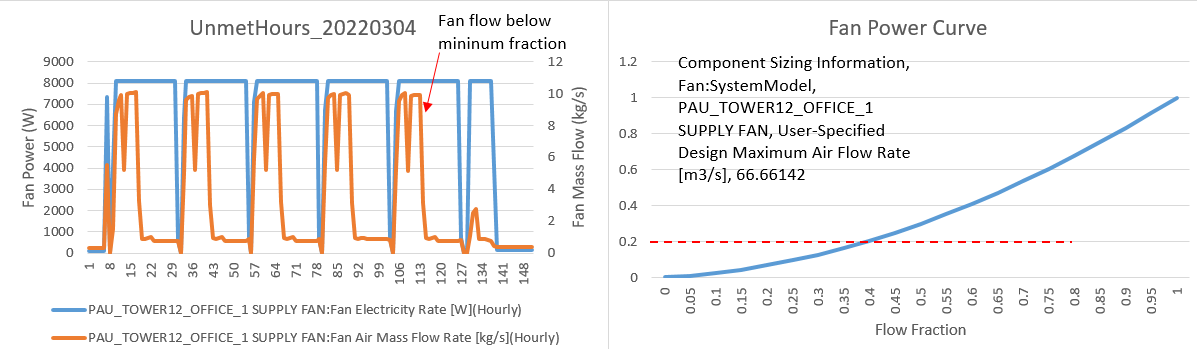
In the fan model the Electric Power Minimum Flow Rate Fraction = 0.2. At flow fractions below 0.2 the fan power will remain constant. At 0 flow the power will go to 0.
Fan:SystemModel,
  PAU_Tower12_Office_1 Supply Fan,  !- Name
  LEED_V4_OFFICE_VENTILATION,  !- Availability Schedule Name
  PAU_Tower12_Office_1 Cooling Coil Outlet,  !- Air Inlet Node Name
  PAU_Tower12_Office_1 Supply Fan Outlet,  !- Air Outlet Node Name
  autosize,                !- Design Maximum Air Flow Rate {m3/s}
  Continuous,              !- Speed Control Method
  0.2,                     !- Electric Power Minimum Flow Rate Fraction
  1200,                    !- Design Pressure Rise {Pa}
  0.9,                     !- Motor Efficiency
  1,                       !- Motor In Air Stream Fraction
| | 3 | No.3 Revision |
Look in the mtd file and find the meters in question. That file will show you what is on each meter. The Heating:EnergyTransfer meter is, if I recall correctly, a sensible only meter. The HeatingCoils:EnergyTransfer is likely total energy transfer, including latent. This would explain why the heating coil energy transfer is larger than heating energy transfer. In fact I just went through this for AHSRAE Std 140 where the html District Heating energy was larger than the Heating:EnergyTransfer and I was confused, until I realized the difference between a meter including latent heat and one that does not.
In the fan model the Electric Power Minimum Flow Rate Fraction = 0.2. At flow fractions below 0.2 the fan power will remain constant. At 0 flow the power will go to 0.
Fan:SystemModel,
  PAU_Tower12_Office_1 Supply Fan,  !- Name
  LEED_V4_OFFICE_VENTILATION,  !- Availability Schedule Name
  PAU_Tower12_Office_1 Cooling Coil Outlet,  !- Air Inlet Node Name
  PAU_Tower12_Office_1 Supply Fan Outlet,  !- Air Outlet Node Name
  autosize,                !- Design Maximum Air Flow Rate {m3/s}
  Continuous,              !- Speed Control Method
  0.2,                     !- Electric Power Minimum Flow Rate Fraction
  1200,                    !- Design Pressure Rise {Pa}
  0.9,                     !- Motor Efficiency
  1,                       !- Motor In Air Stream Fraction
| | 4 | No.4 Revision |
Look in the mtd file and find the meters in question. That file will show you what is on each meter. The Heating:EnergyTransfer meter is, if I recall correctly, a sensible only meter. The HeatingCoils:EnergyTransfer is likely total energy transfer, including latent. This would explain why the heating coil energy transfer is larger than heating energy transfer. In fact I just went through this for AHSRAE Std 140 where the html District Heating energy was larger than the Heating:EnergyTransfer and I was confused, until I realized the difference between a meter including latent heat and one that does not.
In the fan model the Electric Power Minimum Flow Rate Fraction = 0.2. At flow fractions below 0.2 the fan power will remain constant. At 0 flow the power will go to 0.
Fan:SystemModel,
  PAU_Tower12_Office_1 Supply Fan,  !- Name
  LEED_V4_OFFICE_VENTILATION,  !- Availability Schedule Name
  PAU_Tower12_Office_1 Cooling Coil Outlet,  !- Air Inlet Node Name
  PAU_Tower12_Office_1 Supply Fan Outlet,  !- Air Outlet Node Name
  autosize,                !- Design Maximum Air Flow Rate {m3/s}
  Continuous,              !- Speed Control Method
  0.2,                     !- Electric Power Minimum Flow Rate Fraction
  1200,                    !- Design Pressure Rise {Pa}
  0.9,                     !- Motor Efficiency
  1,                       !- Motor In Air Stream Fraction


