First time here? Check out the Help page!
 | 1 | initial version |
The example file you mention shows how it's done, take a better look at it.
What these nodes should be will depend on the 'Fan Placement' you picked in ZoneHVAC:WindowAirConditioner (cf I/O Reference Guide)
This input field has two choices: BlowThrough or DrawThrough. The first choice stands for “blow through fan”. This means that the unit consists of an outdoor air mixer followed by a fan followed by a DX coil. The fan “blows through” the DX coil
So assuming a blow through situation, the ZoneHVAC:WindowAirConditioner's Air Inlet Node Name should be the Return Air Stream Node Name of the OutdoorAirMixer object that's referenced (which is also the Zone Return Air Node...). The Air Outlet Node Name should the the outlet node of the DX Cooling Coil that is used.
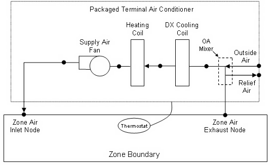
In a Drawthrough situation, yourZoneHVAC:WindowAirConditioner looks exactly like this drawing, except the heating coil doesn't exist:

The ZoneHVAC:WindowAirConditioner's Air Inlet Node Name should be the Return Air Stream Node Name of the OutdoorAirMixer object that's referenced (which is also the Zone Return Air Node...), like above.
The Air Outlet Node Name should the the outlet node of the Fan that is used.
