Question-and-Answer Resource for the Building Energy Modeling Community
| | 1 | initial version |
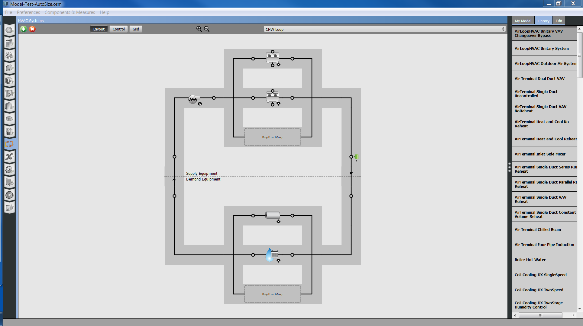
OK, so I was doing a comparison of a water-cooled dual chiller, dual tower Variable Primary loop with Parallel Evaporator/Parallel Condenser, Series Evaporator/Parallel Condenser and Series Evaporator/Series Condenser, respectively.
Parallel Evaporator/Parallel Condenser:
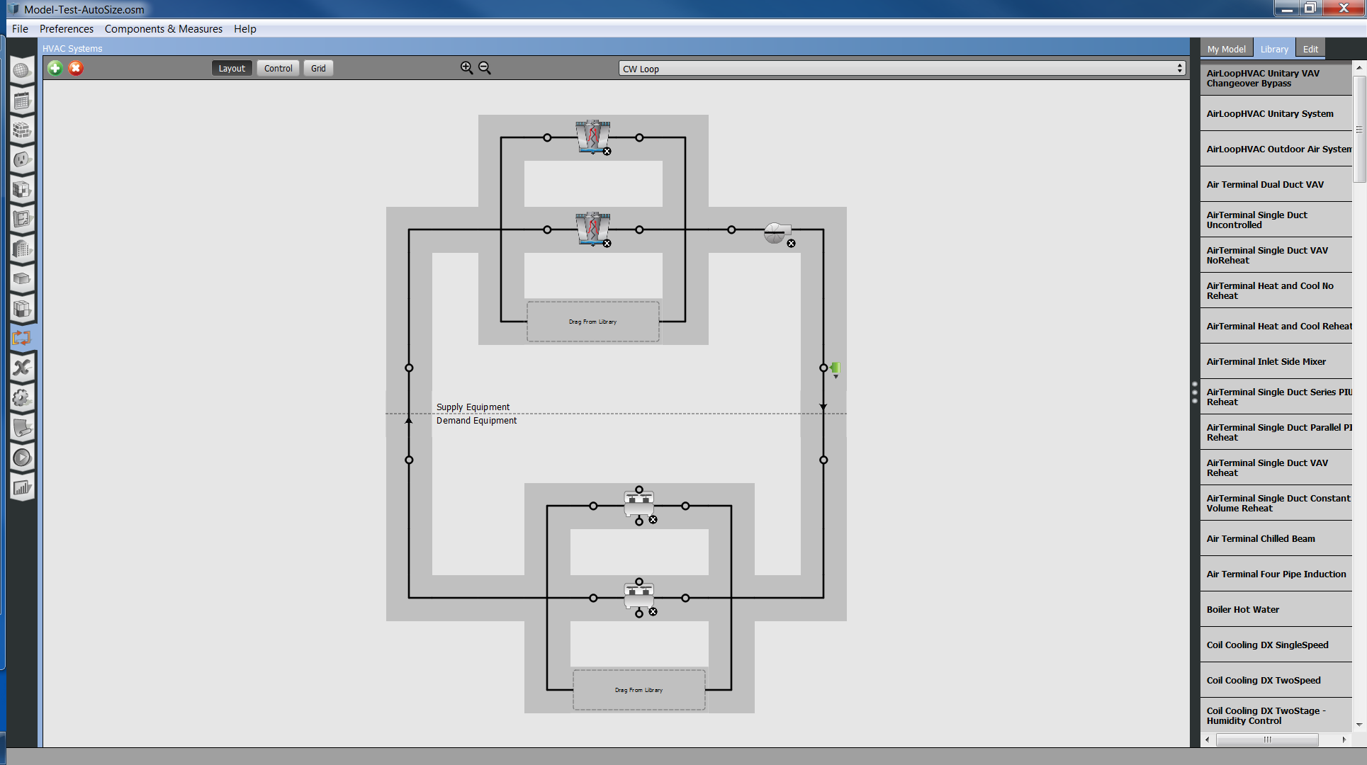
Series Evaporator/Parallel Condenser:

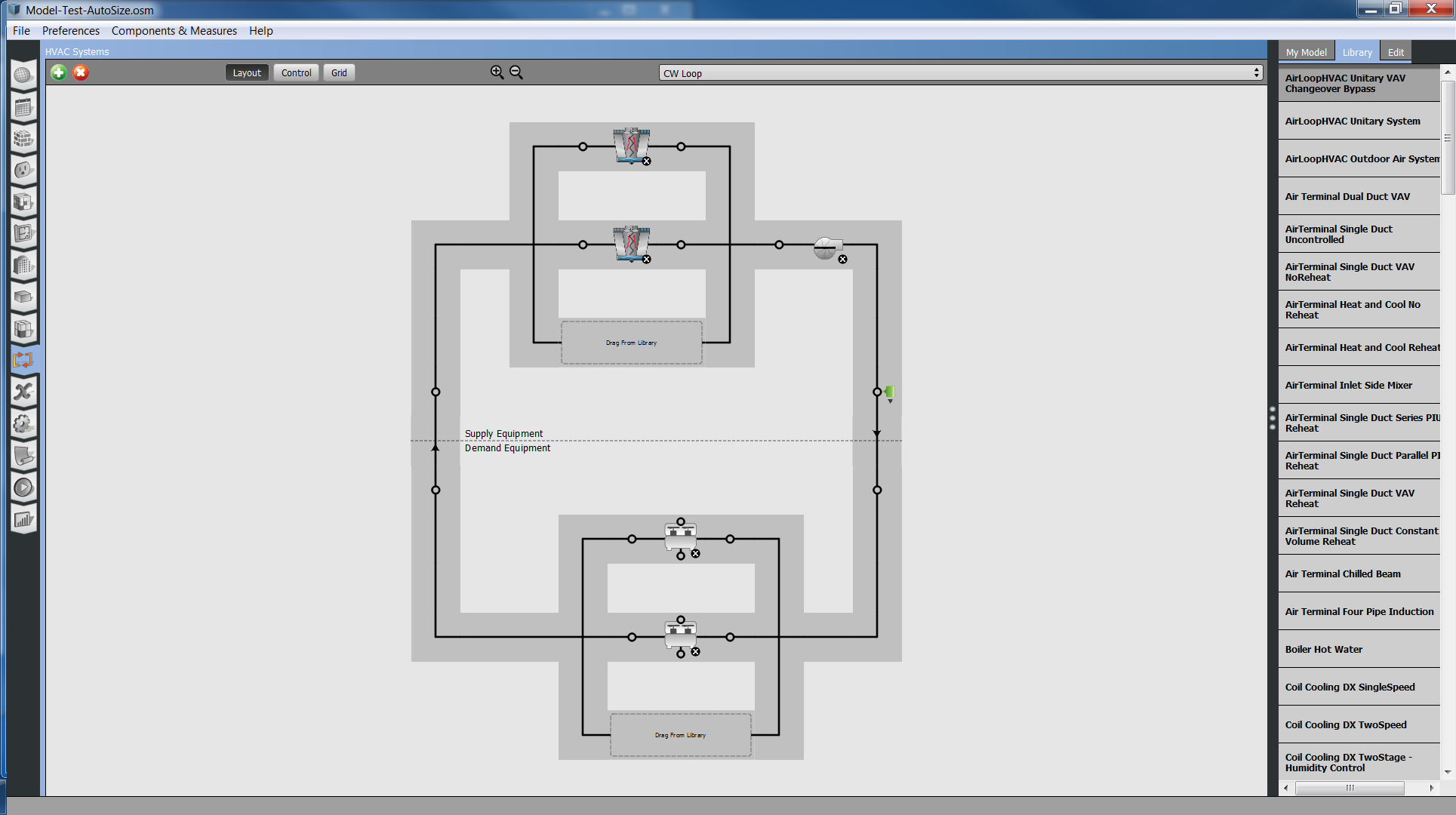
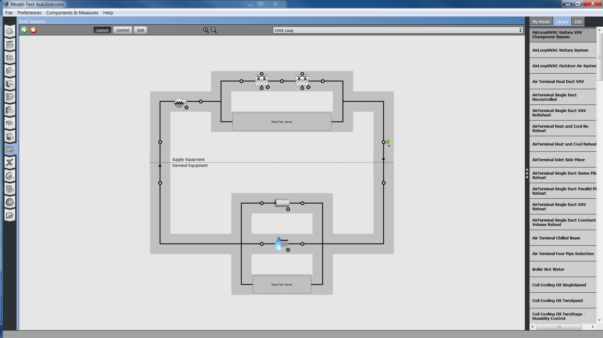
Series Evaporator/Series Condenser:
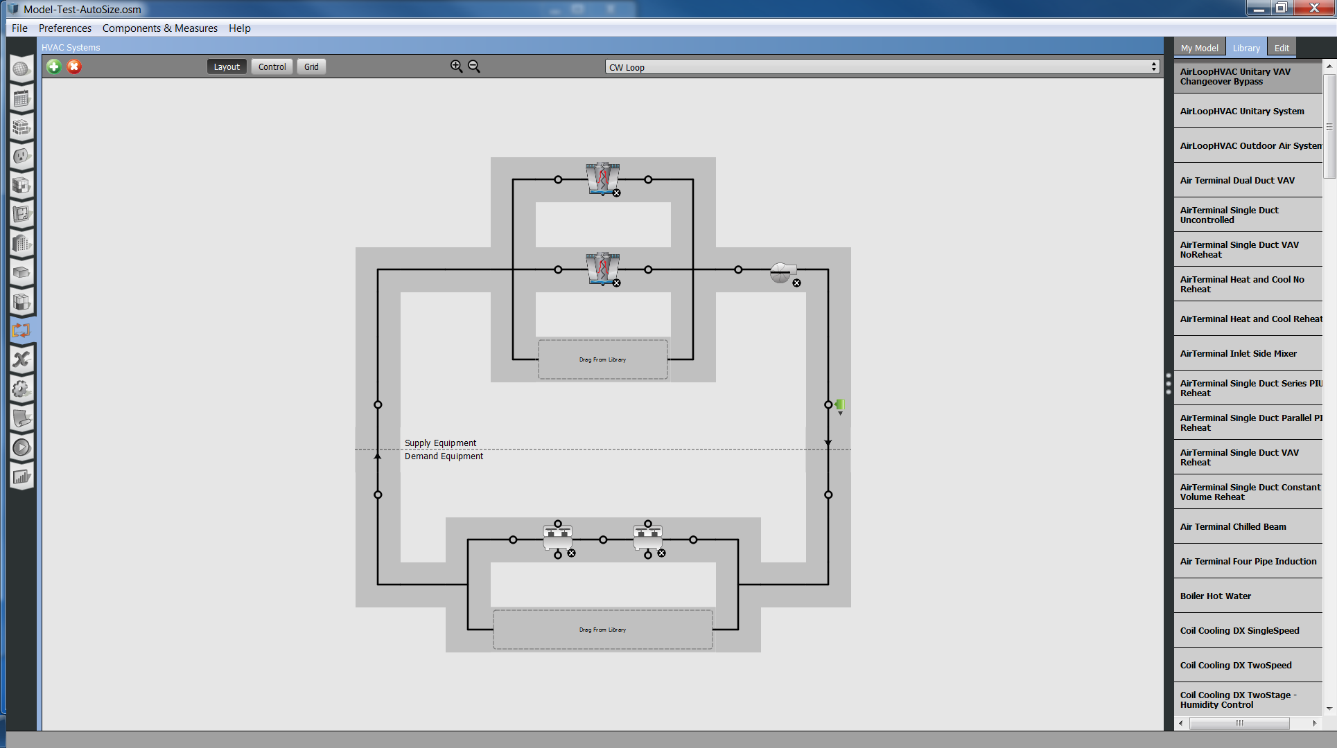
I did all of this with Auto-Sizing everywhere. I had to use the following sizing factors and loop temperature differences (in red) to not only get plausible equipment sizes but to then also get plausible flow rates and temperature differences for the annual simulation runs.
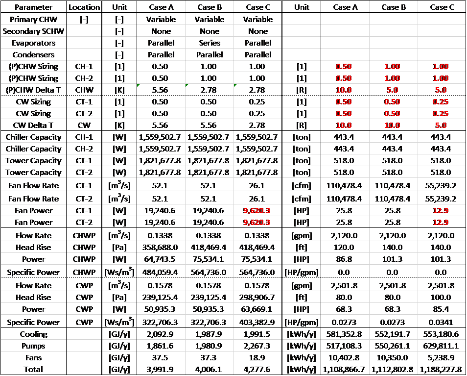
I find this extremely odd, but then again, I do not really know how the (plant) sizing details work. Also note that the fan flow rate and fan power for the series condenser Case C is highly suspect, too, certainly due to the weird sizing factors and loop temperature differences I forced onto this.
I am just curious whether I am way out in the tall weeds with this, or whether there is some system behind these sizing factors and loop temperature differences? As I pointed out earlier, hard-sizing all of this spits out the right equipment sizes, but not the right flow rates during the annual simulation. Auto-sizing per the above does spit out (seemingly?) plausible results in turn.

